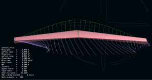
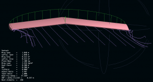
This new plane is for a slope soaring wing which I can mount the head tracker in and then convert it into a powered craft once it’s sloping well.
A name? Name, name ….. errrm name? Something nonsense word not readily used in English which we can make into a proper noun.
Hmmm.. “Sentach”, a quick images.google.com search. Nothing too offensive in there. “Yesss, that’ll dooooo!!!”
I’ll see if I can use XFLR5 this time.
OK we need a Reynolds number (Re) which is this number which allows us to compare a full size commercial air plane to our RC model and roughly know that they are similar. All you need is flow speed, viscosity and chord length to get your Reynolds number. All the foil design software programs use a Reynolds in some way or another.
For our RC plane I’ll work on a 20kt wind at 20 degree temperature which gives a rough Re of 152,207.
Setting up the foil:
Keep the 50mm thickness as much as possible.
Central foil to be asymmetric. say 1% camber.
3.25% L.E. radius.
Thick point at 30% from the L.E.
We have 50mm thick foam at a 300mm chord = 16.6% wing thickness.
T.E (trailing Edge ) thickness 5/300 = 1.67%
XFLR8 software
Well, I’m impressed!!!! Stream analysis on GNU software. Amazing!!
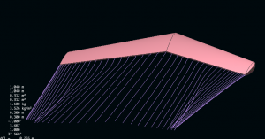
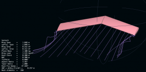
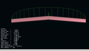
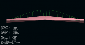
These following images show the difference in lift (the green lines coming up from the wing) and tip vortex when we put 7 degrees tip twist on the wing. It’s considerably less drag. Less lift with the tip twist, but the lift vectors are centralized around the middle of the wing. Thus the wing will handle better, not tip stall, handle more wind and self stabalise quicker.
This video by Chrsto T outlines how to make XFLR8 work this magic.
These images explain quite well how Gemot works.
Notes:
Cm = Pitching moment coefficient –> At Zero the wing is stable. +ve pitch nose up and -ve pitch nose down.
Links:

