Category: Sentach
Dubious GY-85 boards and HMC5883L fix

I ordered 3 different GY-85 boards from 3 different suppliers to find that all of them had the wrong magnetometer in them. Some even advertised their product with the HMC5883L chipset on them, but when they arrived they where the QMC5883L chipset.
After all this effort to find something without the shipping cost / time from the USA I decided to just get the HMC5883L individually and attach it to the I2C bus of the GY-85 board. The individual boards is called the GY-271. I found this supplier in Chullora in Sydney:
GY-271 HMC5883L
It worked just fine and now the head tracker is working.
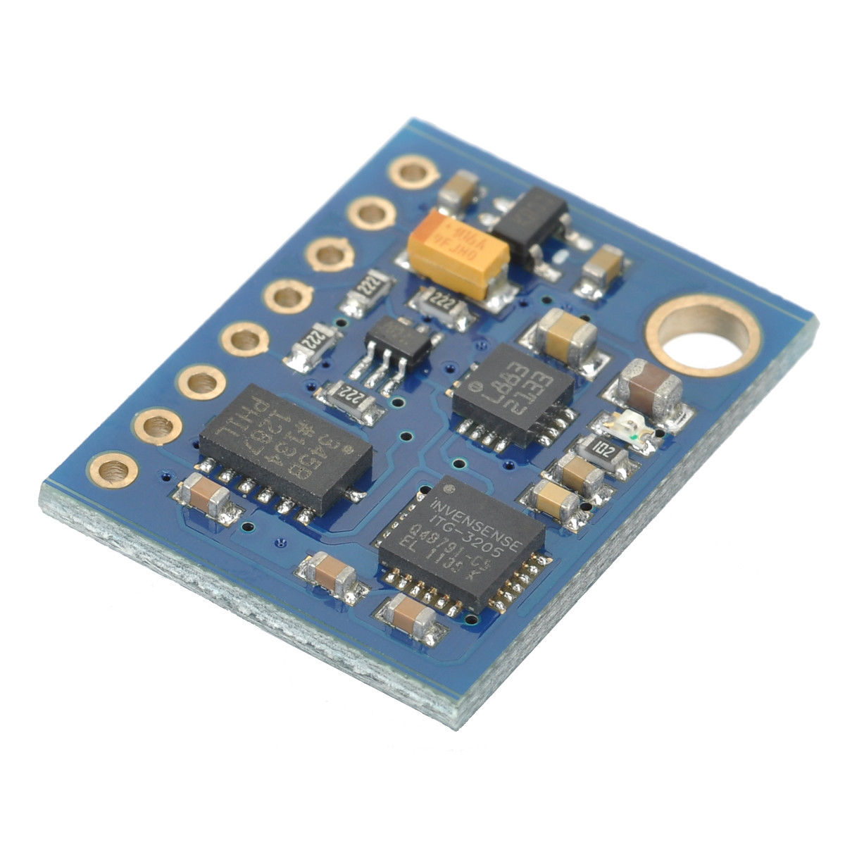
You’ll see in the image below that the Honeywell HMC5883L chip is defined with the markings
L883
2133
Where as the 6th page of the QMC 5883L manual shows the markings something like
DX
5883
XXXX
Using the GY-271 compass board by itself
(Also posted in RC groups)
Roughing out a feasible delivery drone.
The above pdf is a very rough estimation of a delivery drone capable of an 8km return flight (16km one way) with a 4kg payload.
Sentach powered up

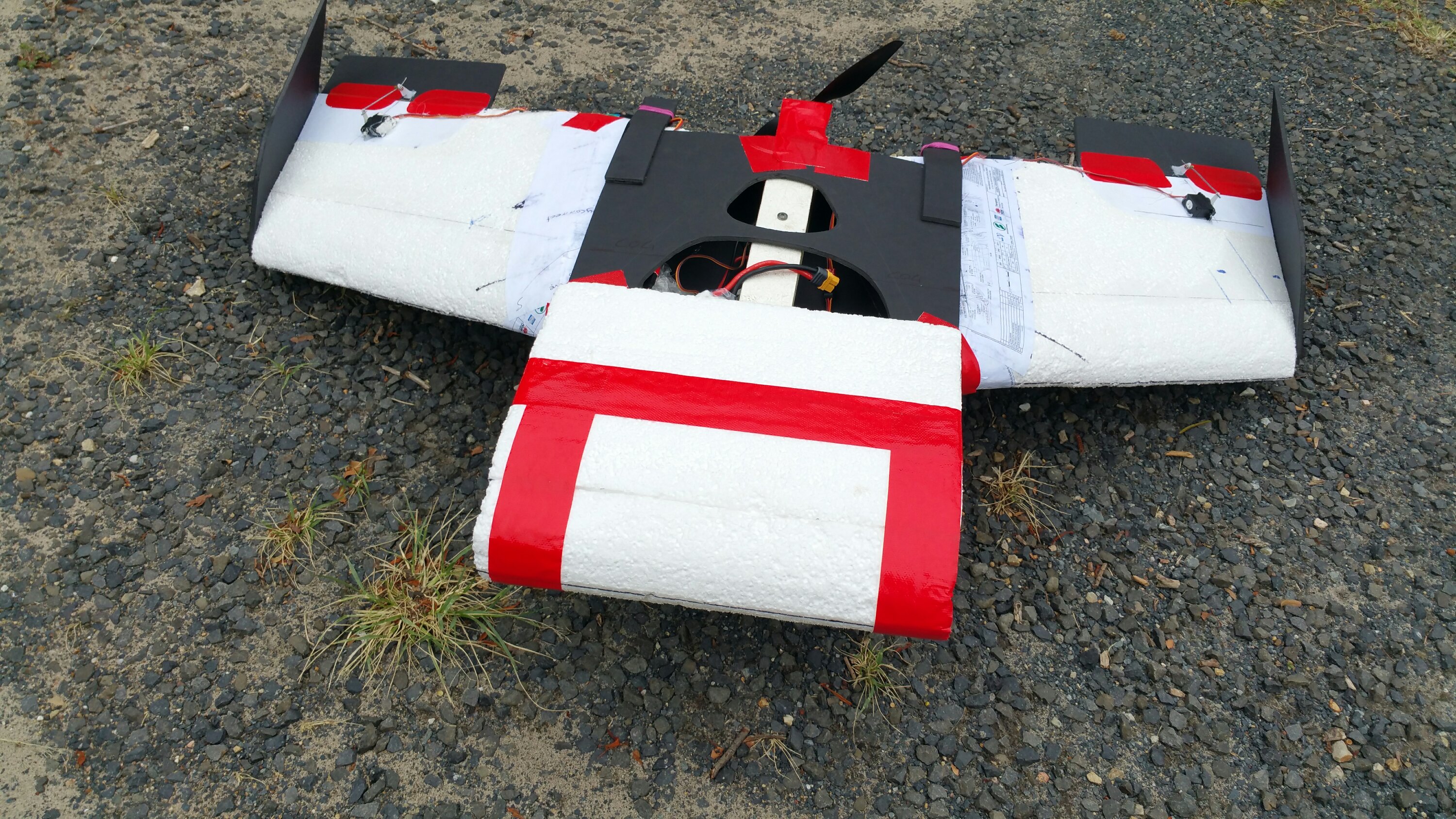

Put the motor in and re-balanced it. Flew at around 14:00ish under power with about a 30kt NNE (15.43m/s) for backup glideability. Flew so well. Only hit about half throttle with a 4s. Had heaps of lift, so I’d say I could max out at about 1kg payload with more throttle. Now onto a flight controller before sticking the head tracker in.
Flight weight – 1414g
New COG – 280mm from the L.E.
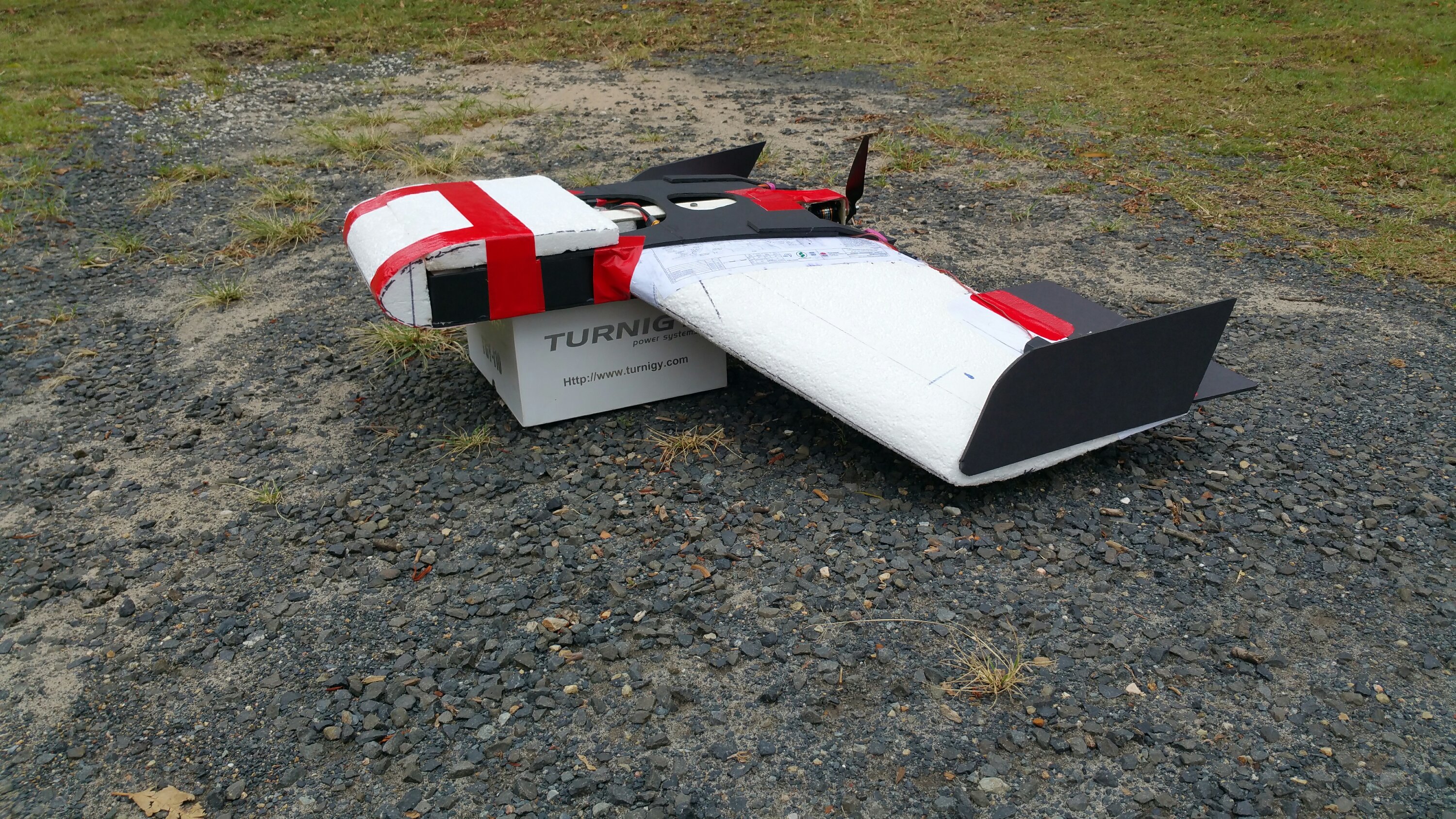
Sentach glider version
The Sentach glider worked well today at the Pat Moreton park in about 15-20kts NNE. Videos to be posted shortly.
Flight weight 680g.
COG 310mm from the L.E.
Beautifully smooth flat landings. Some wobbles as expected. The’s alot of drag points. Especially with the flat sides of the nose. Don’t think anhedral would totally fix it because of the nose as it’s obvioualy turbulating when a crosswind happens.
Crashes it once and the wing popped off nicely dispursing the impact force. Plugged it back together and went again.
The angled wingtips wouldn’t stop the tip vortex as XFLR5 shows in the sim.s. would be better to round into them like Gemot. The difference they made to Gemot was nothing short of impressive. Holding Gemots wing in one hand whilst spinning around, with and without wingtips gives a tactile feeling of the drag differnce involved.
More to come soon.
The current tip foil for Sentach
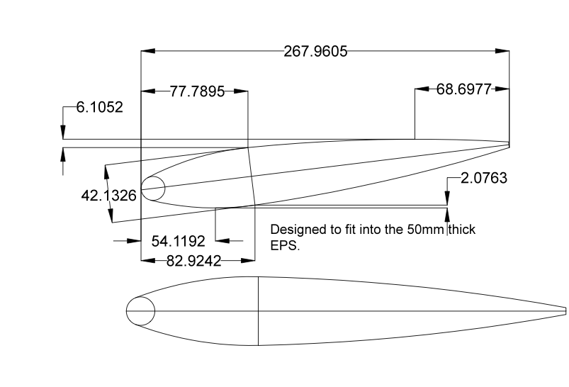
Being a bit too fried to do a proper stability analysis for Sentach, but having enough mind to sketch out the dimensions for the tip twist foil, the above shape emerged.
Designed to fit into the 50mm thick EPS sheet at 7degrees. It should kill the lift and thus tip vortex nicely. Same as Gemot, however Gemot is 7degrees and a far slower and more tolerant foil.
After watching all of the tutorial videos on XFLR5 yesterday I might do a stabilty analysis first…. Hmm maybe…. I also just want to test the head tracker and Sentach is a rough wing, not a refined design.
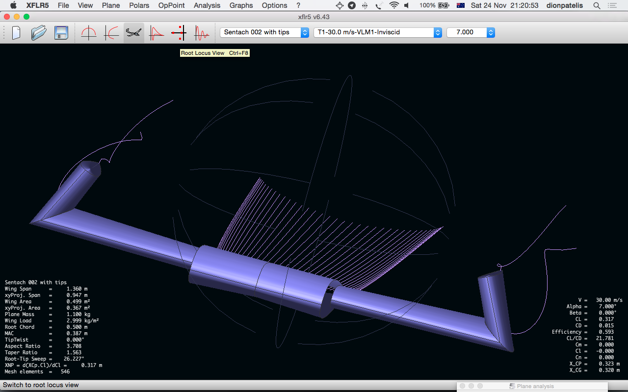
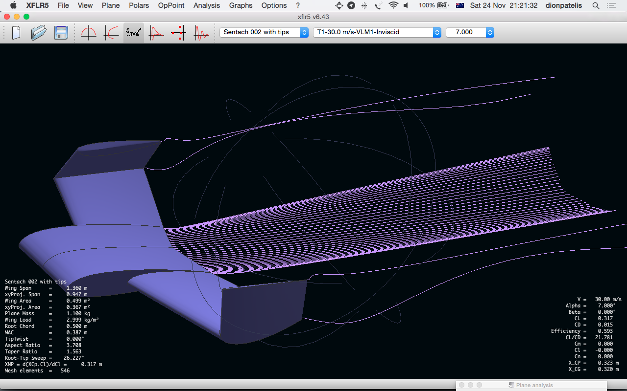
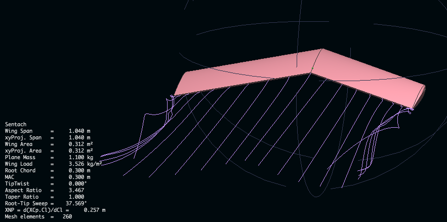
Further Sentach analysis
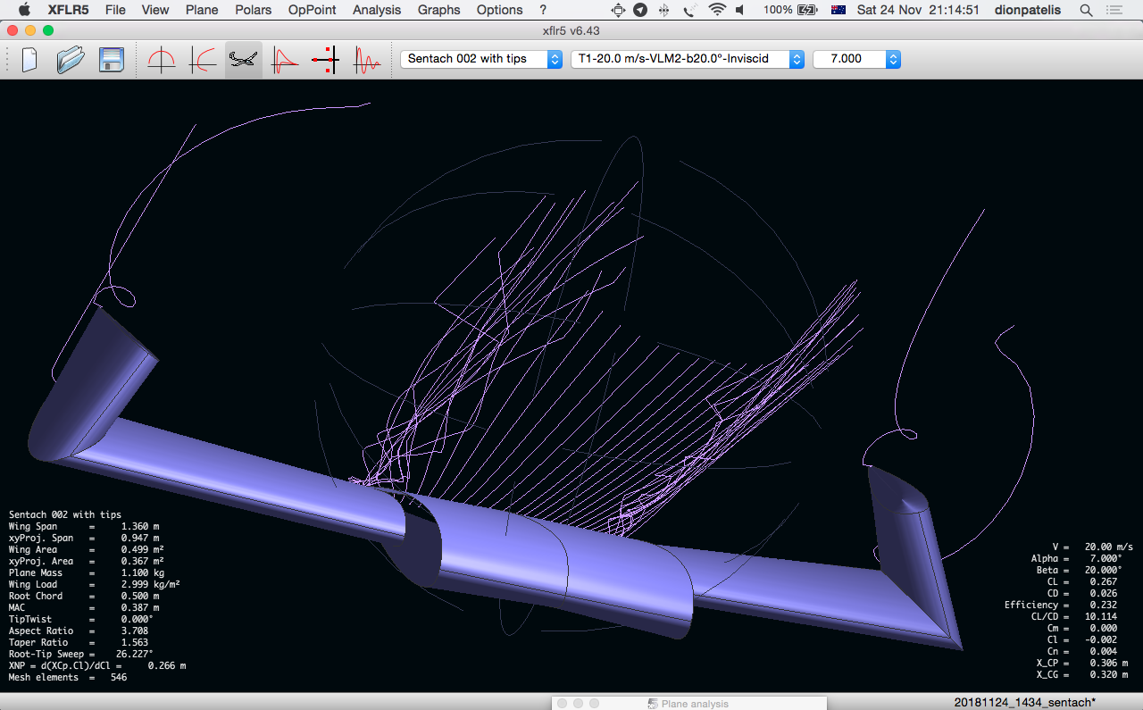
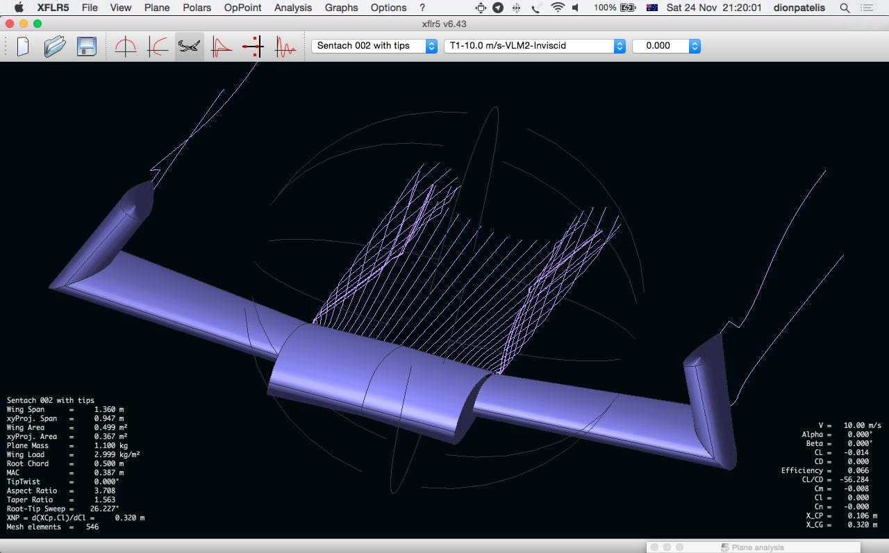
Playing around with XFLR5 I had a good time with inviscid flows, but no such luck with viscous flows. Either way it helps with visualising flows. I don’t know if the vorticies around the fuselage you see in the following images are that true to form at 10m/s. At 20 m/s (40kts) it’s probably more real. Then again we can’t expect too much from 90 degree corners anywhere around the front of an airfoil.
All in all I think 7 degrees for the wingtips will be fine. After all this is meant to be a rough wing just to carry some extra weight for the FPV head tracker.
Interestingly it seemed to say the centre of lift was around 330mm back. We’ll see how that goes.


Calculating out the angle for the wingtips of Sentach
This new plane is for a slope soaring wing which I can mount the head tracker in and then convert it into a powered craft once it’s sloping well.
A name? Name, name ….. errrm name? Something nonsense word not readily used in English which we can make into a proper noun.
Hmmm.. “Sentach”, a quick images.google.com search. Nothing too offensive in there. “Yesss, that’ll dooooo!!!”
I’ll see if I can use XFLR5 this time.
OK we need a Reynolds number (Re) which is this number which allows us to compare a full size commercial air plane to our RC model and roughly know that they are similar. All you need is flow speed, viscosity and chord length to get your Reynolds number. All the foil design software programs use a Reynolds in some way or another.
For our RC plane I’ll work on a 20kt wind at 20 degree temperature which gives a rough Re of 152,207.
Setting up the foil:
Keep the 50mm thickness as much as possible.
Central foil to be asymmetric. say 1% camber.
3.25% L.E. radius.
Thick point at 30% from the L.E.
We have 50mm thick foam at a 300mm chord = 16.6% wing thickness.
T.E (trailing Edge ) thickness 5/300 = 1.67%
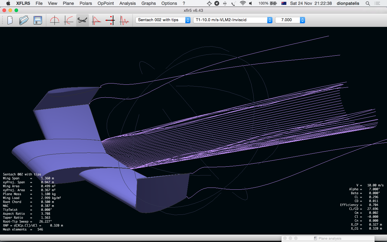
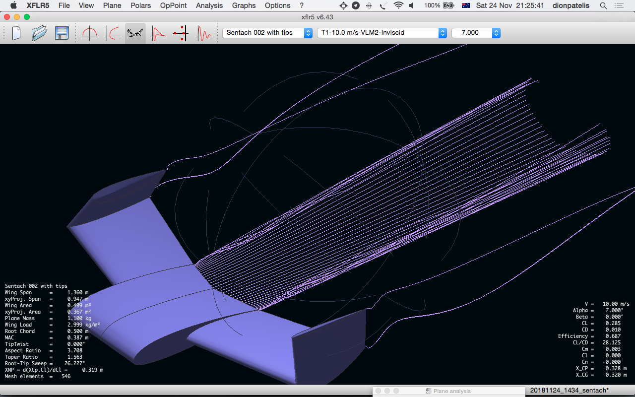
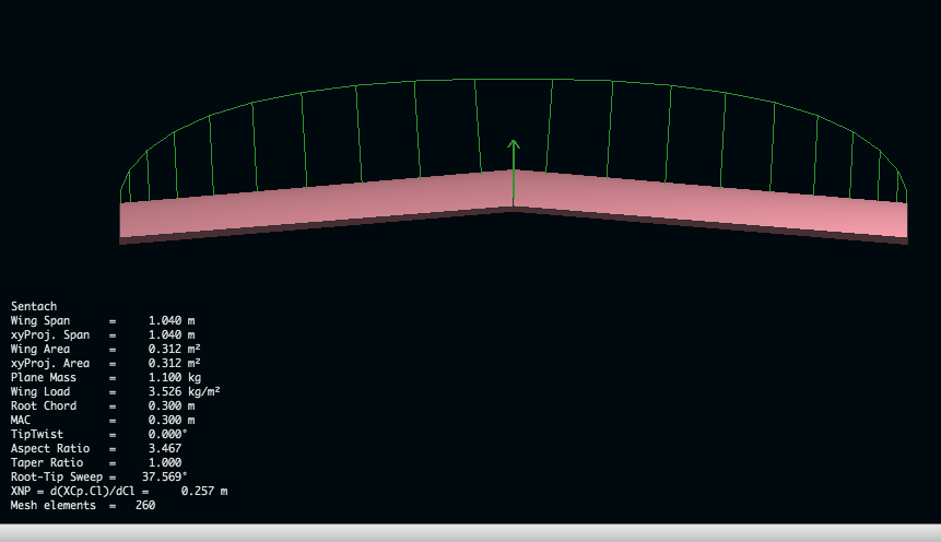
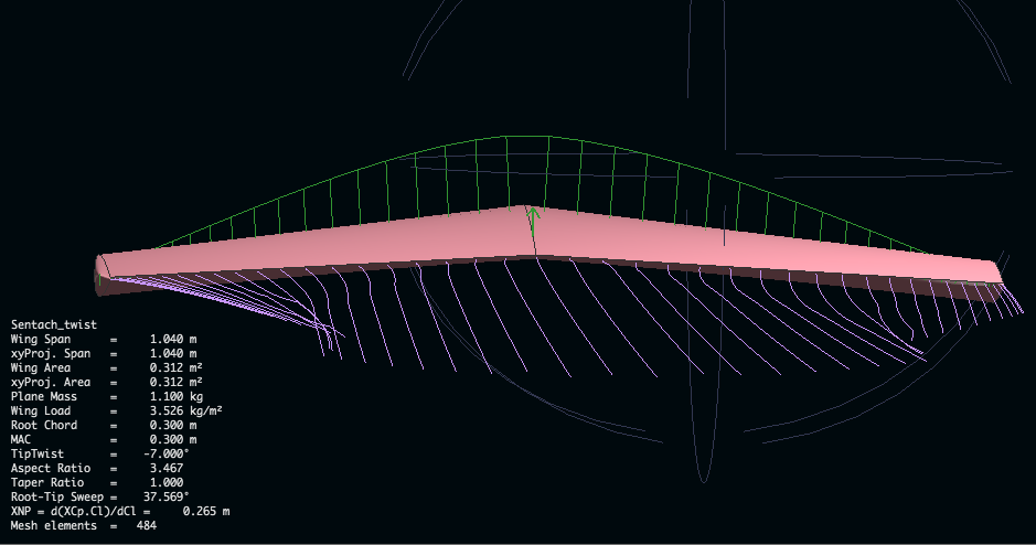
XFLR8 software
Well, I’m impressed!!!! Stream analysis on GNU software. Amazing!!
These following images show the difference in lift (the green lines coming up from the wing) and tip vortex when we put 7 degrees tip twist on the wing. It’s considerably less drag. Less lift with the tip twist, but the lift vectors are centralized around the middle of the wing. Thus the wing will handle better, not tip stall, handle more wind and self stabalise quicker.
This video by Chrsto T outlines how to make XFLR8 work this magic.
These images explain quite well how Gemot works.


Notes:
Cm = Pitching moment coefficient –> At Zero the wing is stable. +ve pitch nose up and -ve pitch nose down.
Links:
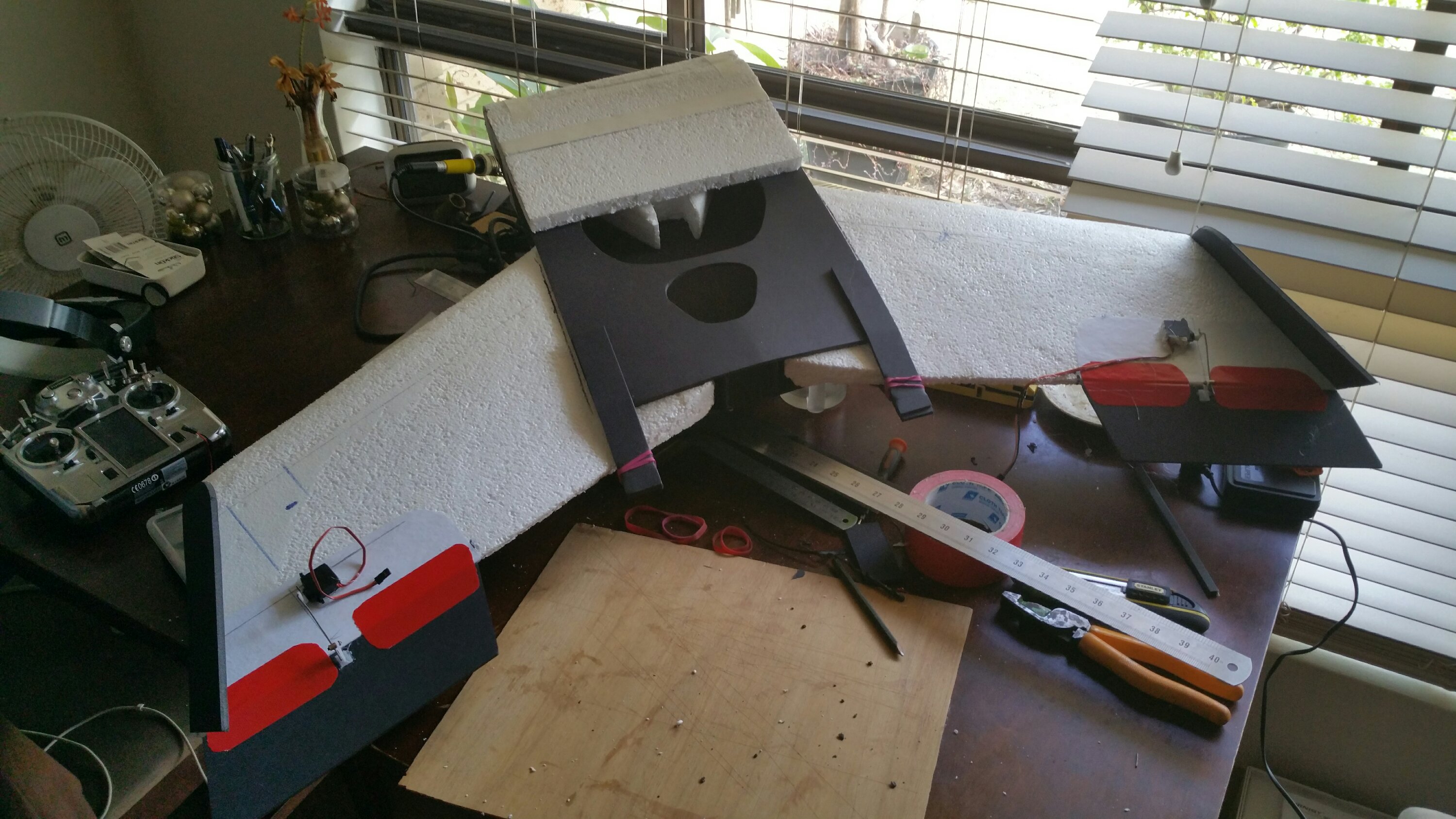
Something to put the head tracker in.
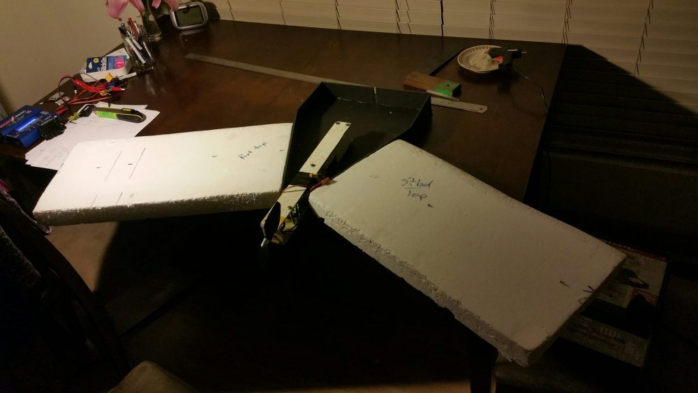
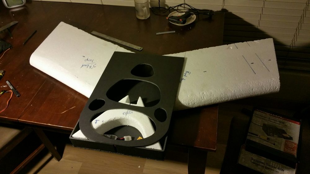
I wanted to put the head tracker in some thing. Gemot would only just allow for the head tracker in it and it only had 35mm maximum air flow distortion (i.e. the thickness of the centre foil). The EPS sheets I’ve been buying are 50mm thick which is plenty of air distortion to create heaps of lift. This wing above will also have the fuselage as part of the lifting surface. It will be the same proportions as the wings. Thus making it about 70ish mm thick.
It’s about the same wingspan as Gemot coming it at just a touch over a metre. I’ve learnt that the little 0.25N torque servos (2.5kg/cm) are straining on almost everything when the wing span is over a metre.
This wing also allows for the GRP (Glass Reinforced Plastic) chassis to be pushed inside to convert it to powered flight later. It can be tested gliding and then step across to powered later by sliding in the engine. The V- shaped EPS frame inside should spread the load on impacts with the ground during testing.
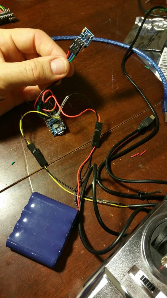
About the head tracker. The HMC5883L chip arrived in the post on Friday and I couldn’t wait. Put it together that night. Added the chip into the I2C bus, Added Dennis Frie’s code and away it went. It worked through the Turnigy i10 using the trainer cable and a 10channel RX.