Posted on

The current tip foil for Sentach

Being a bit too fried to do a proper stability analysis for Sentach, but having enough mind to sketch out the dimensions for the tip twist foil, the above shape emerged.

Designed to fit into the 50mm thick EPS sheet at 7degrees. It should kill the lift and thus tip vortex nicely. Same as Gemot, however Gemot is 7degrees and a far slower and more tolerant foil.

After watching all of the tutorial videos on XFLR5 yesterday I might do a stabilty analysis first…. Hmm maybe…. I also just want to test the head tracker and Sentach is a rough wing, not a refined design.

Posted on

Where are the EAPs?

Electro Active Polymers. Where are they?

I seem to continuously be looking for linear actuator which are small, light, fast and not a bastardisation of a rotational or solenoid device. The synthetic muscle so to speak. I saw one on the television show ‘Beyond 2000’ about 20 years ago and remember thinking “right, a revoltion of mechanics is here”.

Obviously not.

I found a thesis of something at Woolongong Uni a couple of years ago and have not followed it up yet.

Either way, if someone knows where I can get EAPS which I can chain in series or parallel with the reaction time of a standard RC servo, please contact me (Dion) via SMS on +61 419 486 672.

Posted on

Viscous effects

This video explains how XFLR5 approximates viscosity using the polar outputs from 2D analysis.

Techwinder says on the above video that it does not do the full complex analysis for viscosity. However at this point it looks like it does a pretty good job. I was satisfied yesterday with the outputs I made. Especially considering I’d not read the manual and was just fumbling around. It did a great job of confirming my approximate estimations for Sentach. Looking at the video manual and other text today, it looks like it could do more than accurate enough estimations for my current projects.

As Techwinder states in the forums, it’s not made to just bring in solid geometry from another package and do CFD on it. However it’s focus is foils and it seems to be very fast at assembling foils and doing to calcs. A massive step up from roughing the calcs out by hand. It should be far faster to design future RC wings like Gemot. Gemot was an estimation based on what I new from hands on experience windsurfing and surfing. I actually didn’t really expect it to fly as well as it did on that first proto which crashed into my van.

Although it took several CNC models before I hit Gemot V3. There was only 2D analysis of the 2 Gemot foils using the Dresler software, where I just looked for the best lift : drag ratio for a specific AOA. That became the tip twist for Gemot. It’s still not perfect, but with XFLR5 I may be able to do more accurate mental prototyping with the software.

Still, I wonder if the Autodesk CFD design handles importing the current .stl files for Gemot V3.

Posted on

Further Sentach analysis

Playing around with XFLR5 I had a good time with inviscid flows, but no such luck with viscous flows. Either way it helps with visualising flows. I don’t know if the vorticies  around the fuselage you see in the following images are that true to form at 10m/s. At 20 m/s (40kts) it’s probably more real. Then again we can’t expect too much from 90 degree corners anywhere around the front of an airfoil.

All in all I think 7 degrees for the wingtips will be fine. After all this is meant to be a rough wing just to carry some extra weight for the FPV head tracker.

Interestingly it seemed to say the centre of lift was around 330mm back. We’ll see how that goes.

Posted on

Calculating out the angle for the wingtips of Sentach

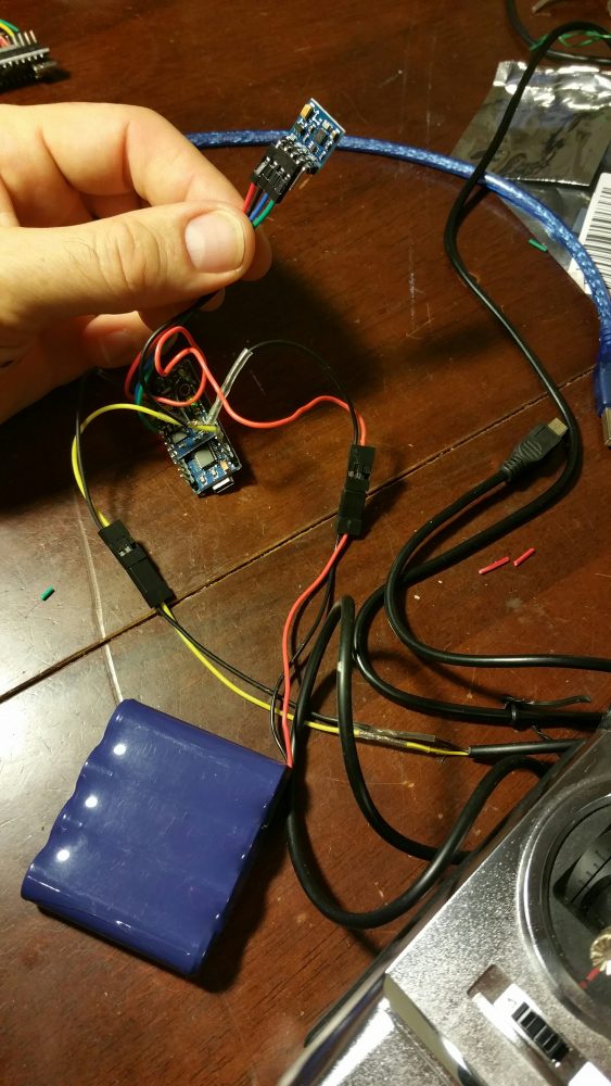
This new plane is for a slope soaring wing which I can mount the head tracker in and then convert it into a powered craft once it’s sloping well.

A name? Name, name ….. errrm name? Something nonsense word not readily used in English which we can make into a proper noun.

Hmmm..   “Sentach”, a quick images.google.com search. Nothing too offensive in there. “Yesss, that’ll dooooo!!!”

I’ll see if I can use XFLR5 this time.

OK we need a Reynolds number (Re) which is this number which allows us to compare a full size commercial air plane to our RC model and roughly know that they are similar. All you need is flow speed, viscosity and chord length to get your Reynolds number. All the foil design software programs use a Reynolds in some way or another.

For our RC plane I’ll work on a 20kt wind at 20 degree temperature which gives a rough Re of 152,207.

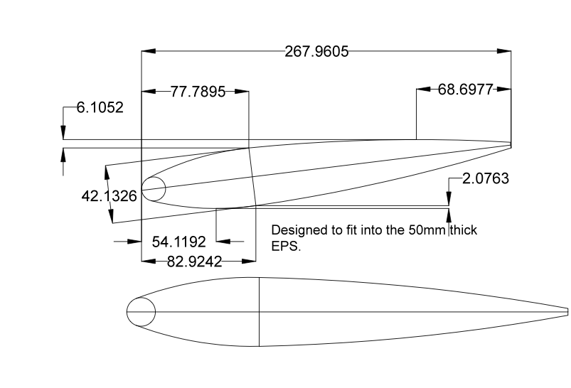
Setting up the foil:

Keep the 50mm thickness as much as possible.

Central foil to be asymmetric. say 1% camber.

3.25% L.E. radius.

Thick point at 30% from the L.E.

We have 50mm thick foam at a 300mm chord = 16.6% wing thickness.

T.E (trailing Edge ) thickness 5/300 = 1.67%
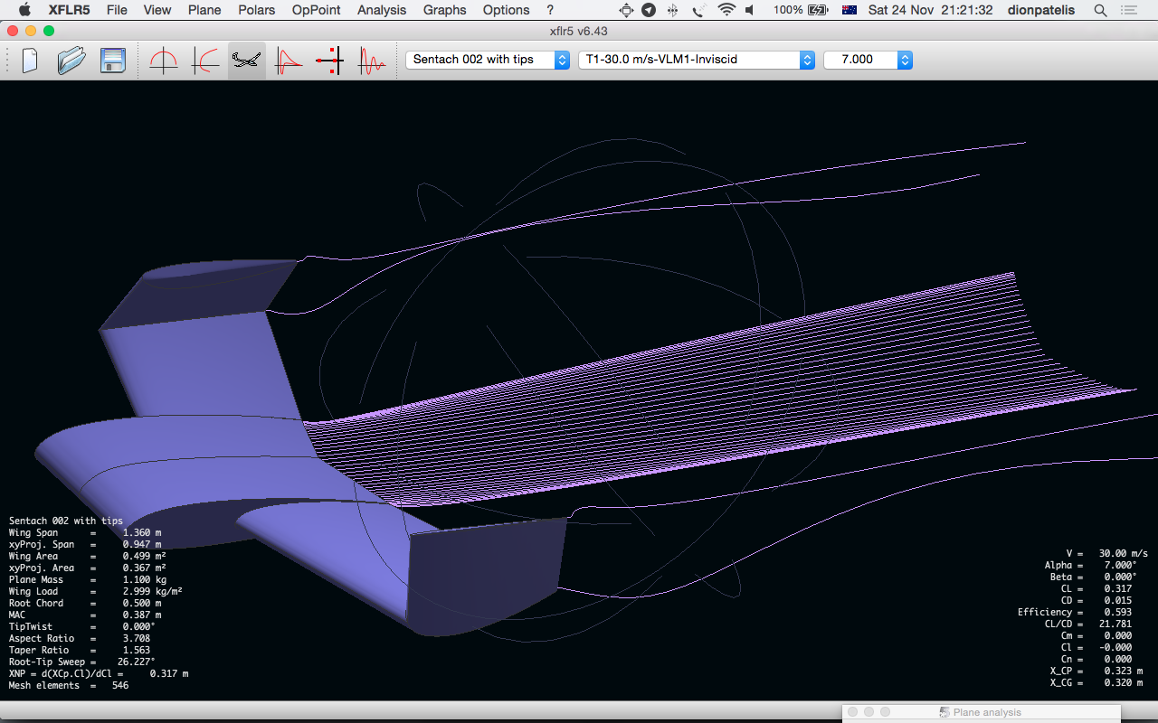
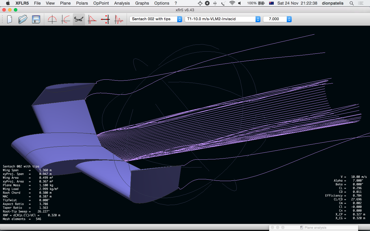
XFLR8 software

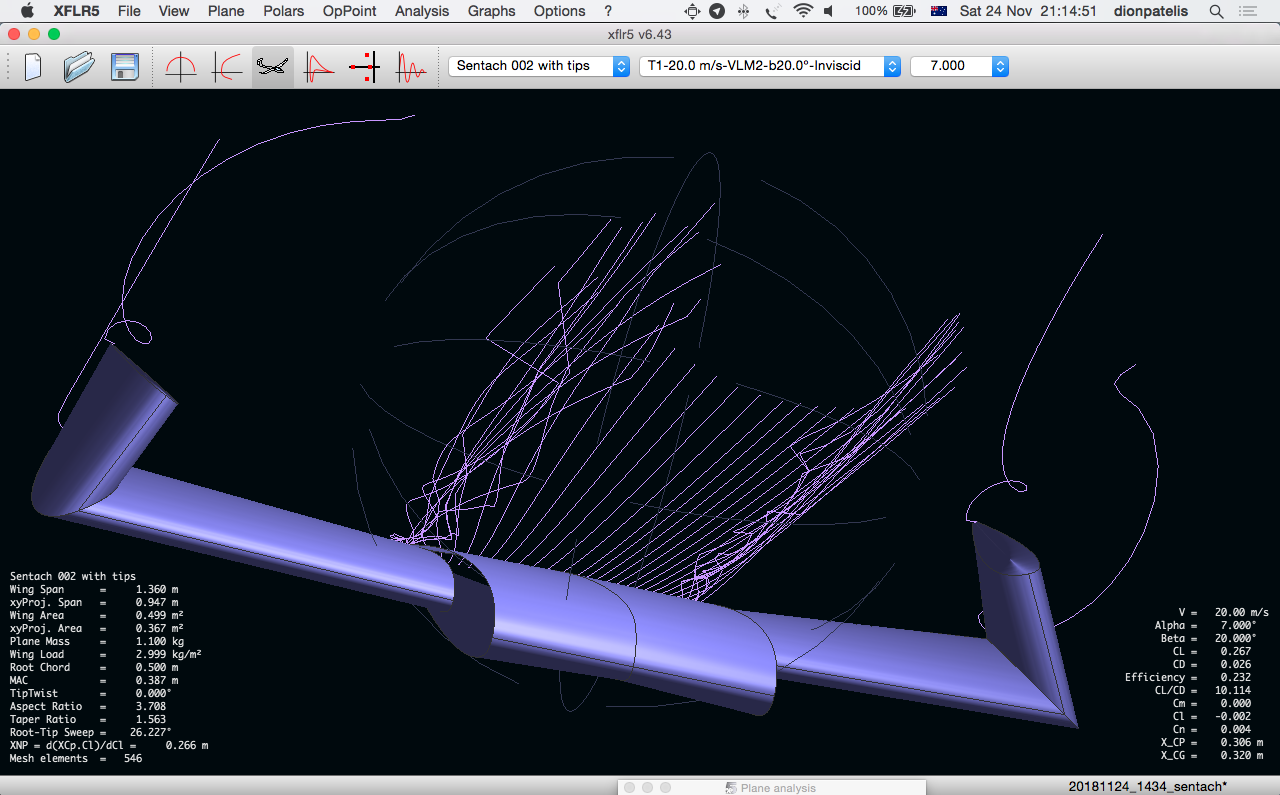
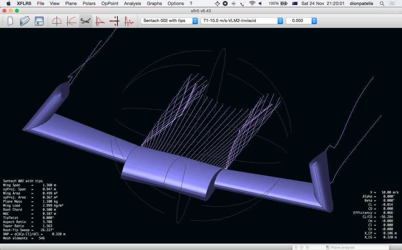
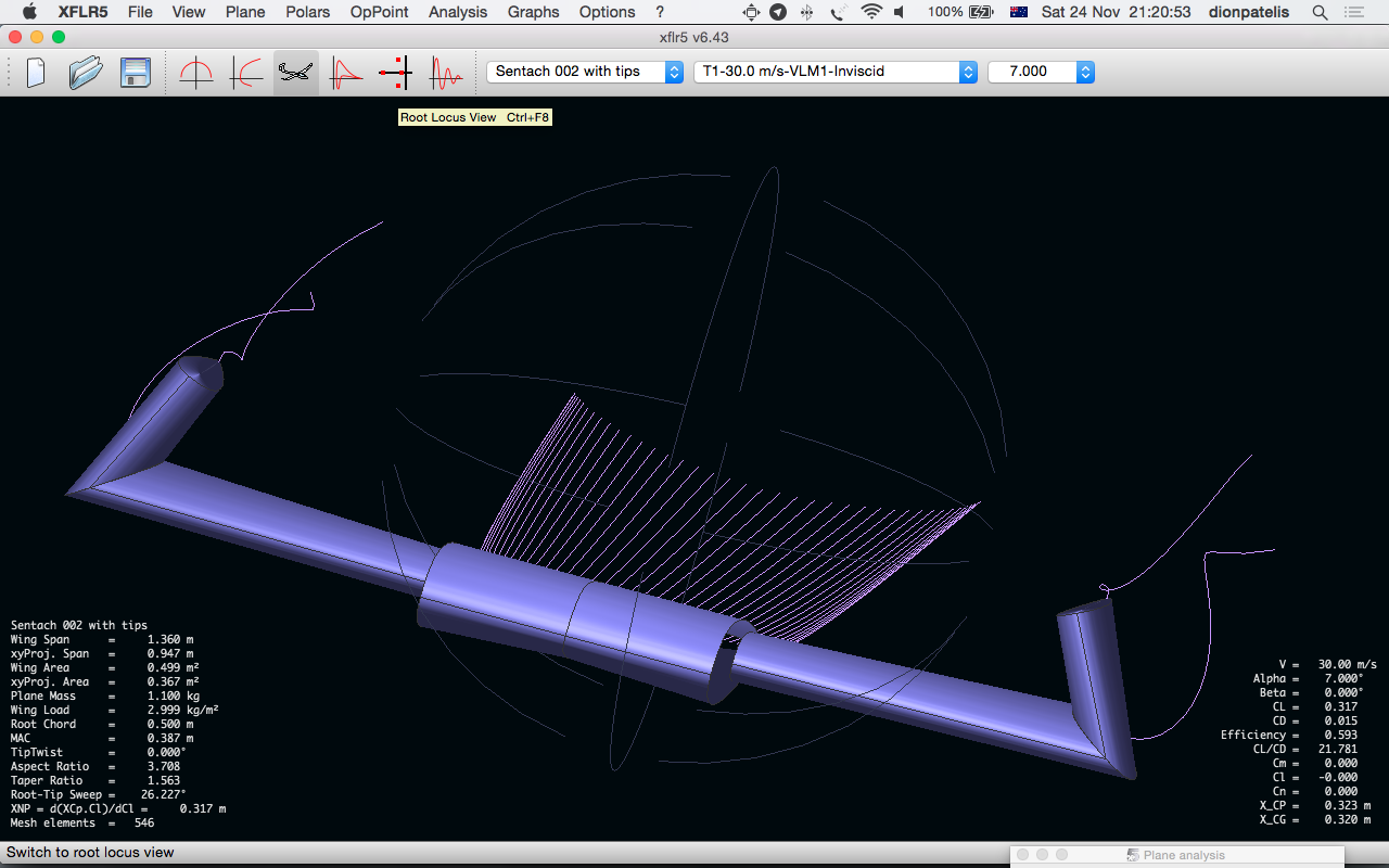
Well, I’m impressed!!!! Stream analysis on GNU software. Amazing!!

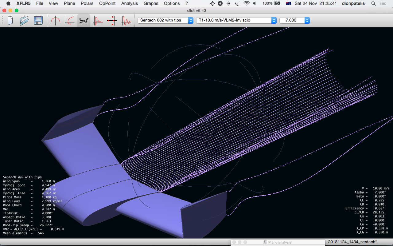
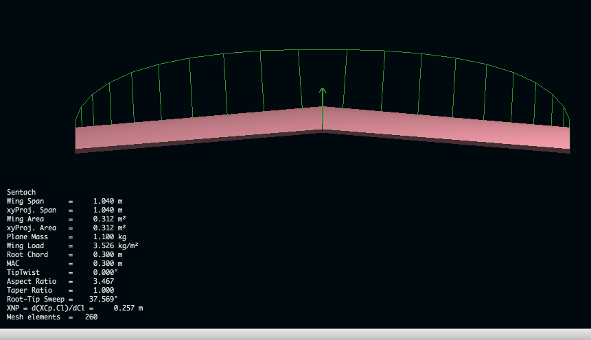
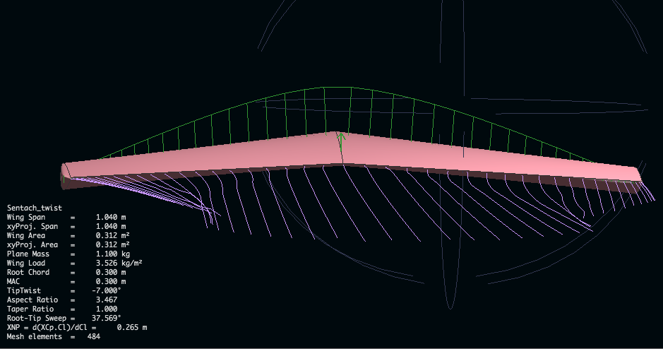
These following images show the difference in lift (the green lines coming up from the wing) and tip vortex when we put 7 degrees tip twist on the wing. It’s considerably less drag. Less lift with the tip twist, but the lift vectors are centralized  around the middle of the wing. Thus the wing will handle better, not tip stall, handle more wind and self stabalise quicker.

This video by Chrsto T outlines how to make XFLR8 work this magic.

These images explain quite well how Gemot works.

Notes:

Cm = Pitching moment coefficient –> At Zero the wing is stable. +ve pitch nose up and -ve pitch nose down.


Links:

Reading Polar diagrams


Posted on

Something to put the head tracker in.

I wanted to put the head tracker in some thing. Gemot would only just allow for the head tracker in it and it only had 35mm maximum air flow distortion (i.e. the thickness of the centre foil). The EPS sheets I’ve been buying are 50mm thick which is plenty of air distortion to create heaps of lift. This wing above will also have the fuselage as part of the lifting surface. It will be the same proportions as the wings. Thus making it about 70ish mm thick.

It’s about the same wingspan as Gemot coming it at just a touch over a metre. I’ve learnt that the little 0.25N torque servos (2.5kg/cm) are straining on almost everything when the wing span is over a metre.

This wing also allows for the GRP (Glass Reinforced Plastic) chassis to be pushed inside to convert it to powered flight later. It can be tested gliding and then step across to powered later by sliding in the engine. The V- shaped EPS frame inside should spread the load on impacts with the ground during testing.

About the head tracker. The HMC5883L chip arrived in the post on Friday and I couldn’t wait. Put it together that night. Added the chip into the I2C bus, Added Dennis Frie’s code and away it went. It worked through the Turnigy i10 using the trainer cable and a 10channel RX.


Posted on

Fried the QX90C mosfet

Yes, by the 4th flight it was baked. The mosfet labelled A08K 77 overheated. I think possibly because we are NoObs at Quad flying and so hovering around indoors on and off the ground without much air movement over the mosfets doesn’t give much of a chance for heat dissipation.

We ordered some mosfets off Ali Express. They should arrive in a couple of months and then we can test our micro soldering skills. Util then we’ve ordered some more QX90C’s and will also order a spare flight control board.

Maybe it’s worth sticking a baby heat sink on these mosfets.

Posted on

Testing the weight shifter.

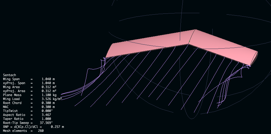
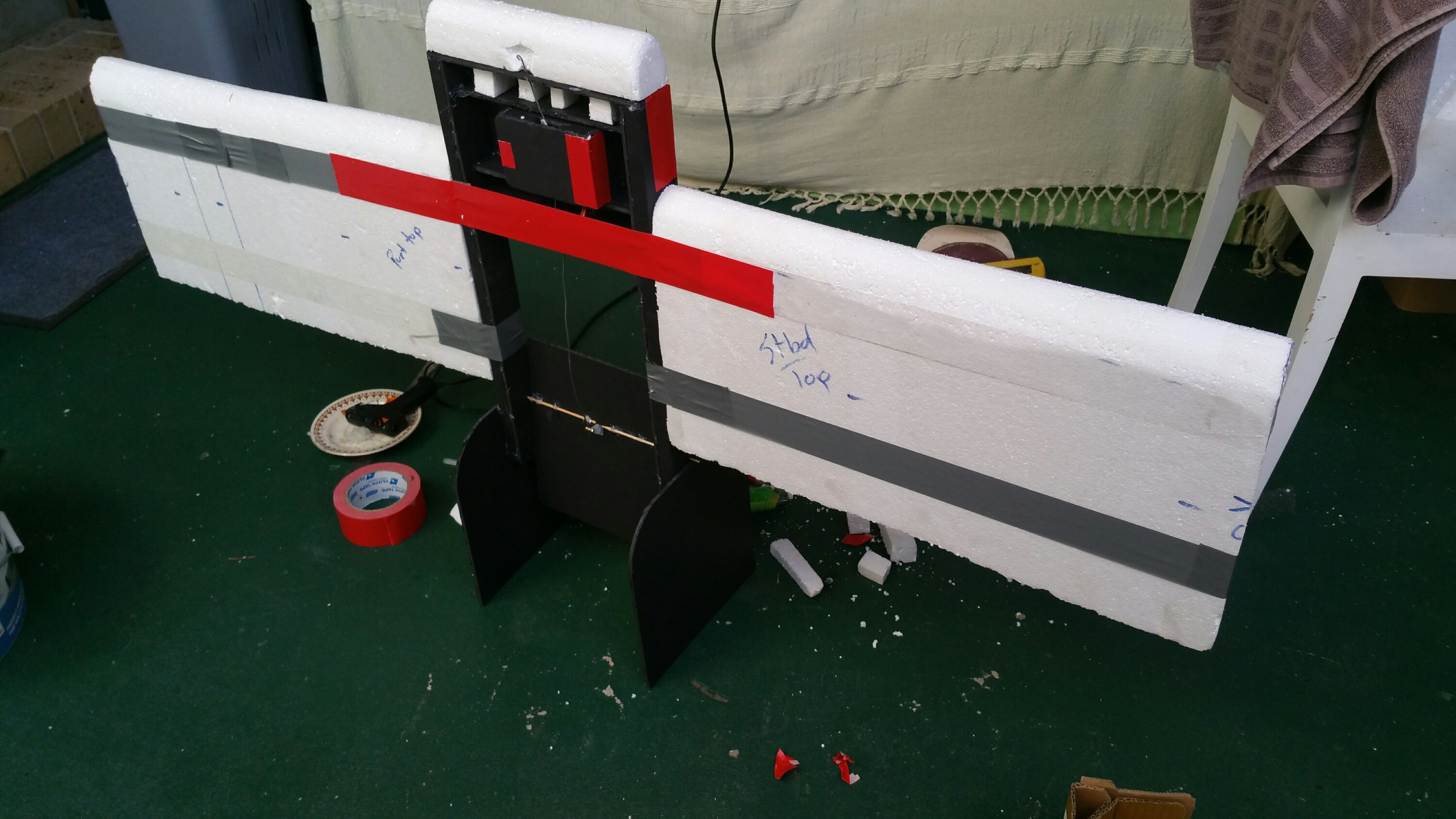
Just tested the weight shifter at skenners. Flew perfectly … in a straight line. Flight weight 836g. Too much lift on these wings. Also the lift goes all the way to the tips rather than being laterally centralised. Thus the weight shift makes bugger all difference in this wing.Using 50mm thick foam sheets as wings is great as you don’t have to laminate them, but then they’re heavy, cause way more lift and require more power, torque, mass movement to drive rhem.