Attempt 2 was quickly cannobalised by attempt 3. Rather than trying to figure out a complete answrr to the universe by thinking about it, just start building.And by just building this the possibility of fore and aft mass shift becomea more apparent.This time the weight shift is only port and starboard. AOA set by a trailing wing.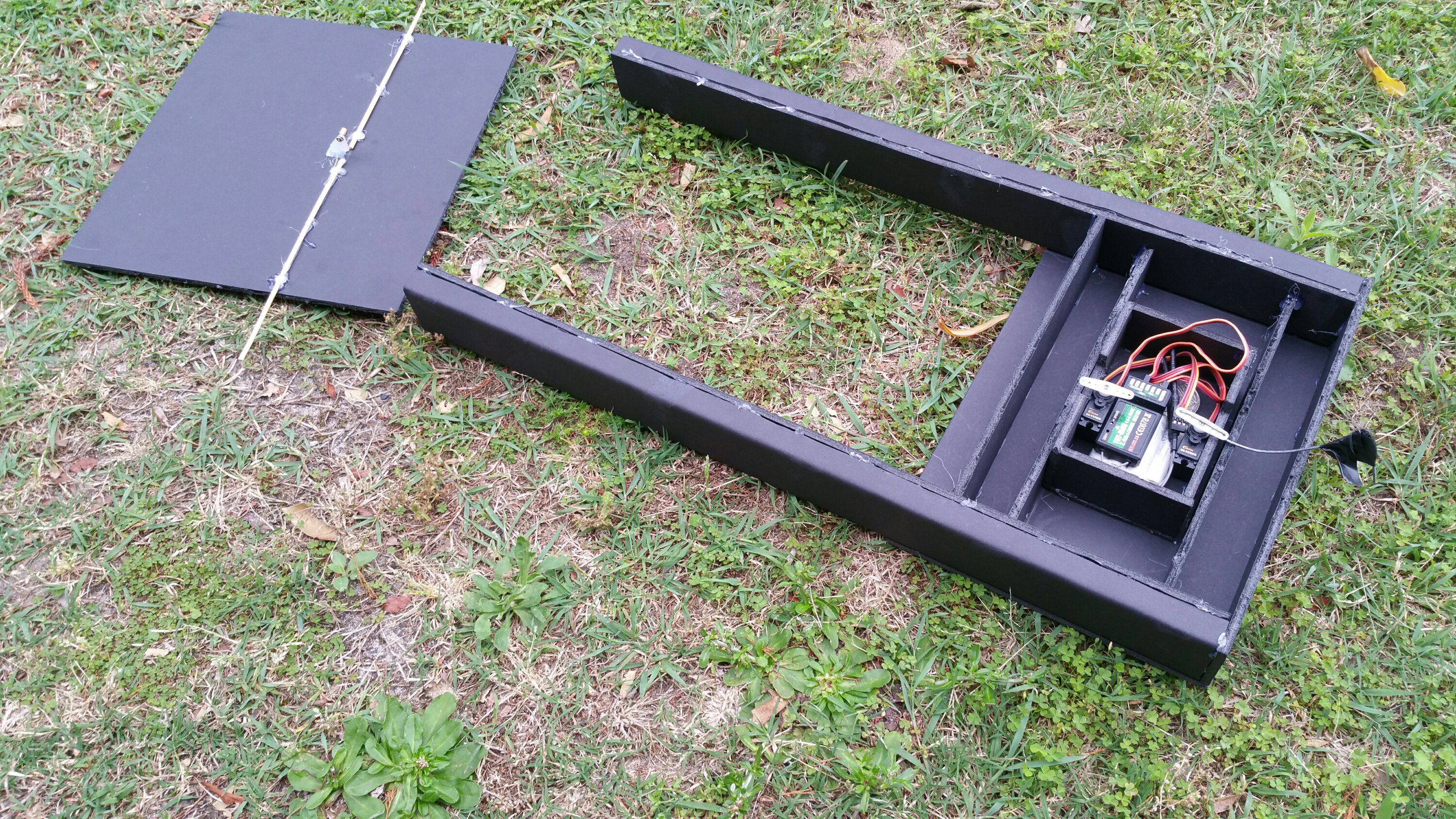
Year: 2018
Another dud GY-85
This is the 4th order of the GY-85 and it has the QMC magneto in it again even though the photos on ebay showed the Honeywell chip. Hmm, bit of a fail. RC groups was saying the Honeywell chip is not manufactured any more.
I got the QMC chip working on all 3 axis’, but it uses a totally different code library and thus Dennis Frie’s code doesn’t work with it. Might be time to write some code??
Weight shifter concept attempt
Objective:
Shift the weight around in the plane, rather than shifting the lift point around using control surfaces (ailerons, elevators, etc).
Purpose:
- Save time on making control surfaces for every wing designed.
- Control the stall point like a hang glider or bird does, to enable controlled stall landings.
- Give the ability to shape and switch wings quickly.
- Reduce the number of weak points caused by embedded servos and control surfaces.
Notes
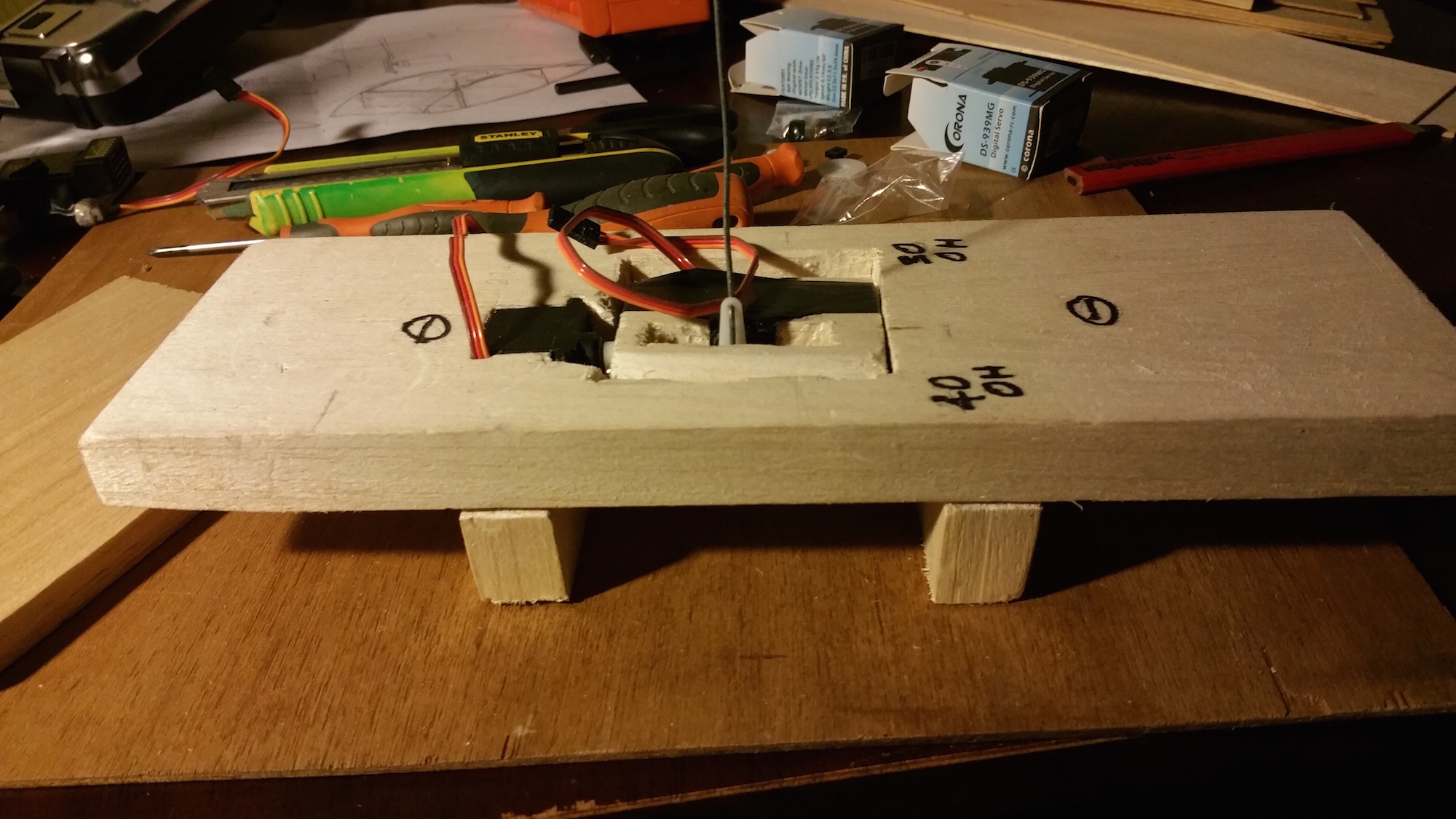
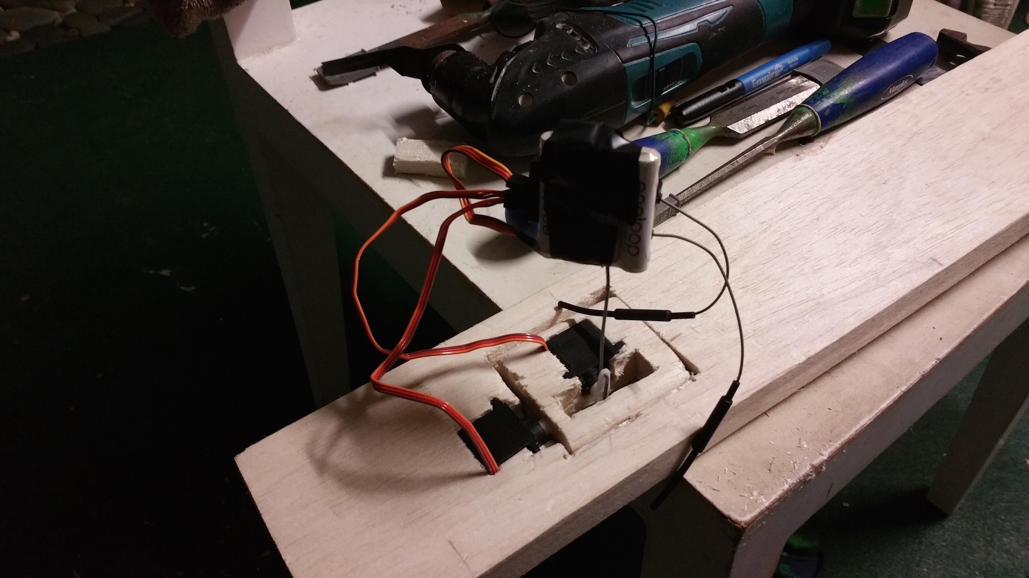
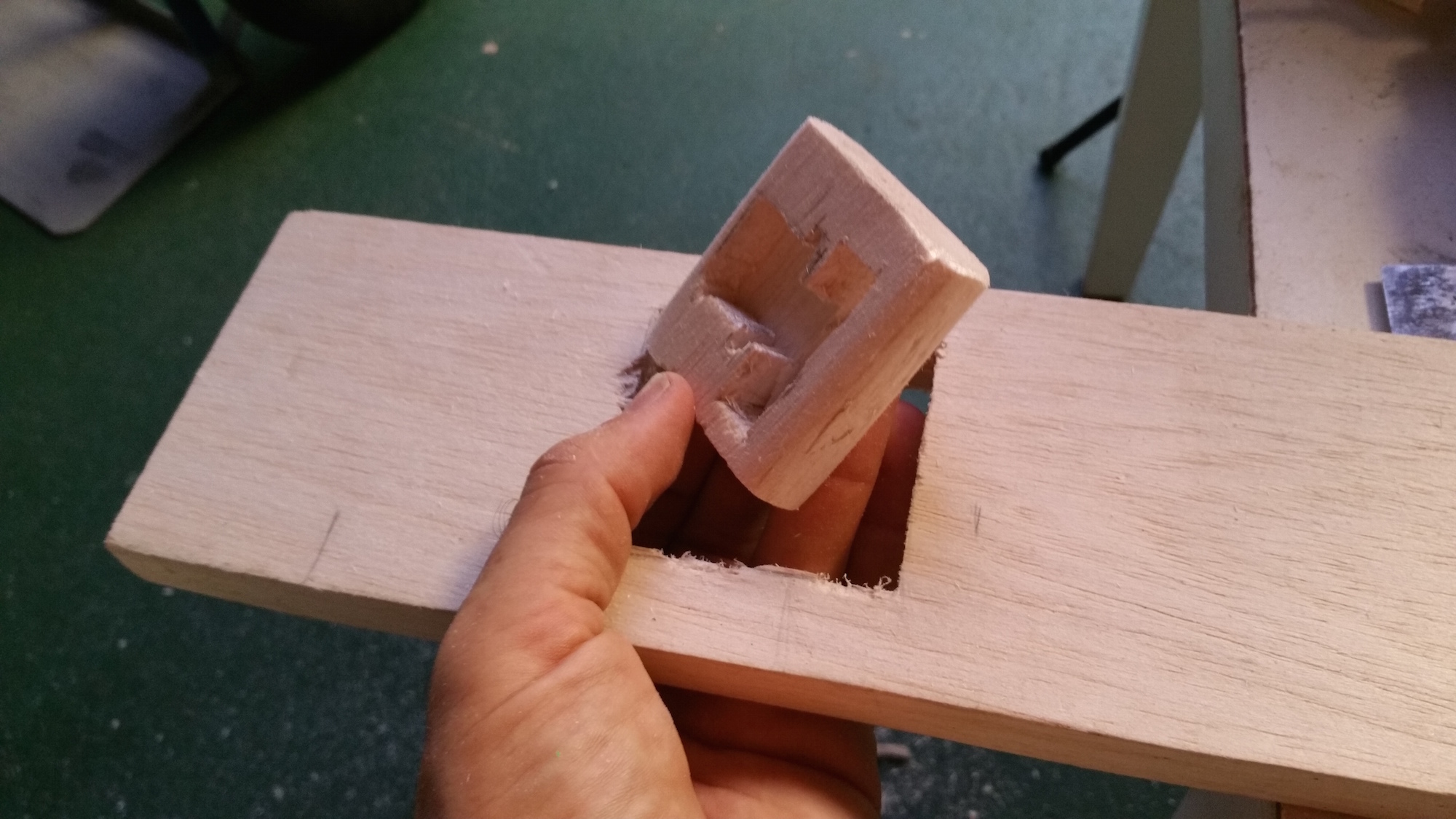
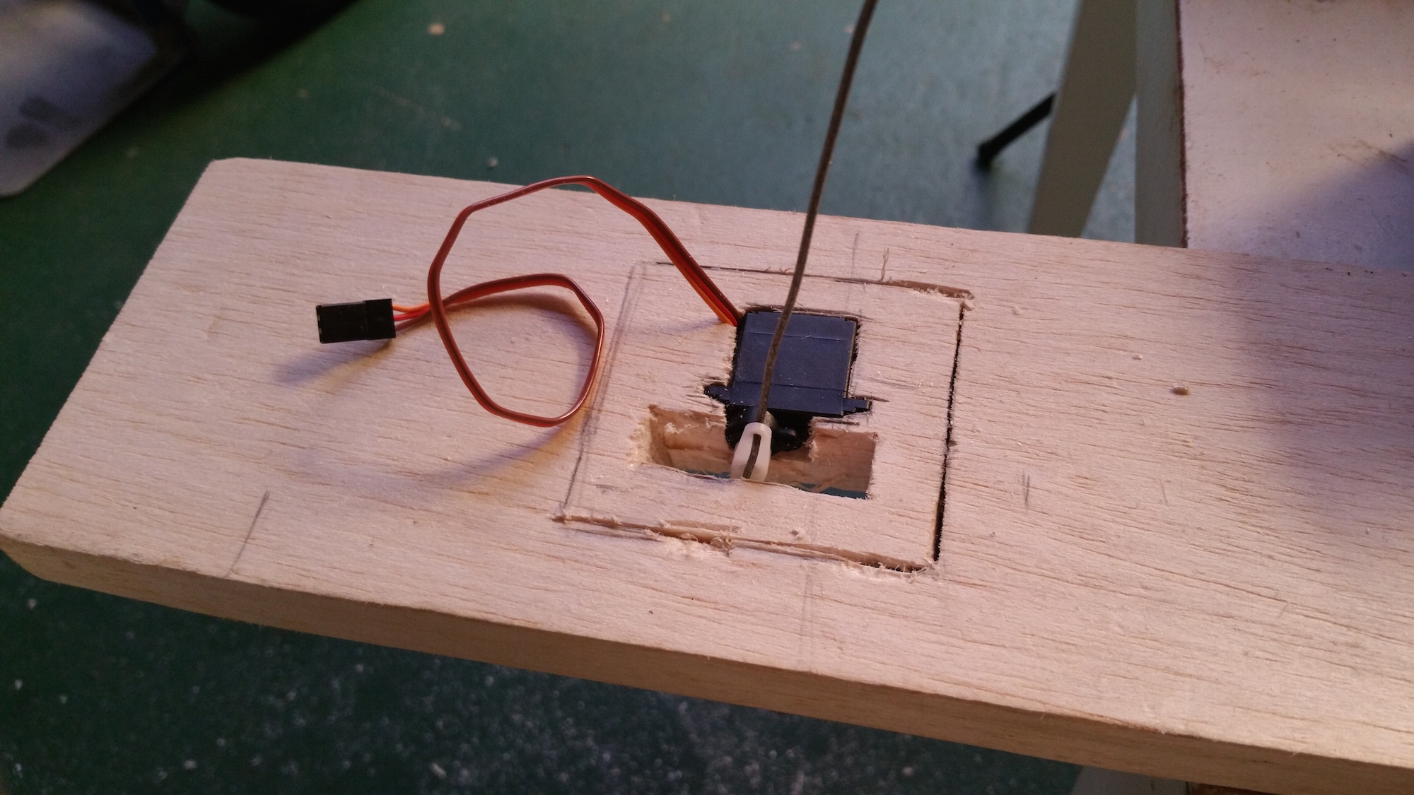
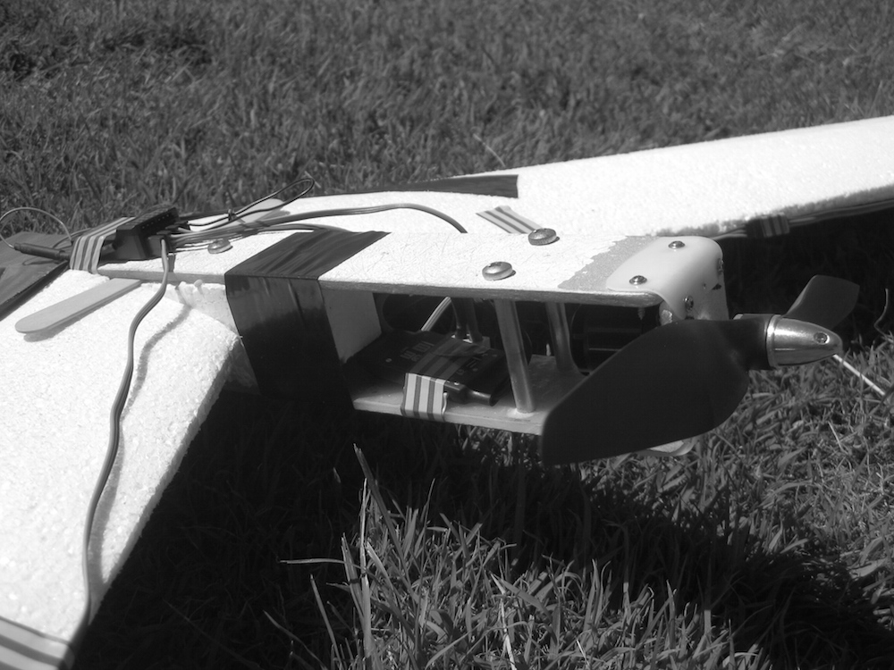
In this attempt on making a flying object which uses weight shift, I decided to use standard servos to see what I could get away with. The stepper motors I want to use would take time to get here and I am impatient on this one.
Definitely the conclusion on the DS939MG servos is that they are not really made for aircraft much bigger than a 1m wingspan. After that the mass just steps up too much and they don’t handle it. Even though I kind of know this when smashing tests together, I do them anyway just to prove concepts.
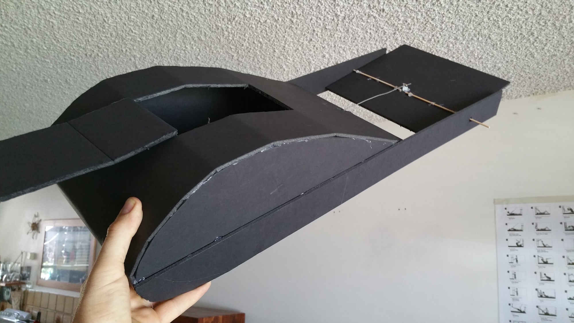
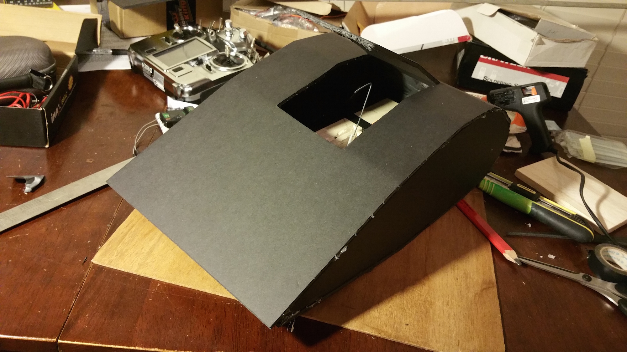
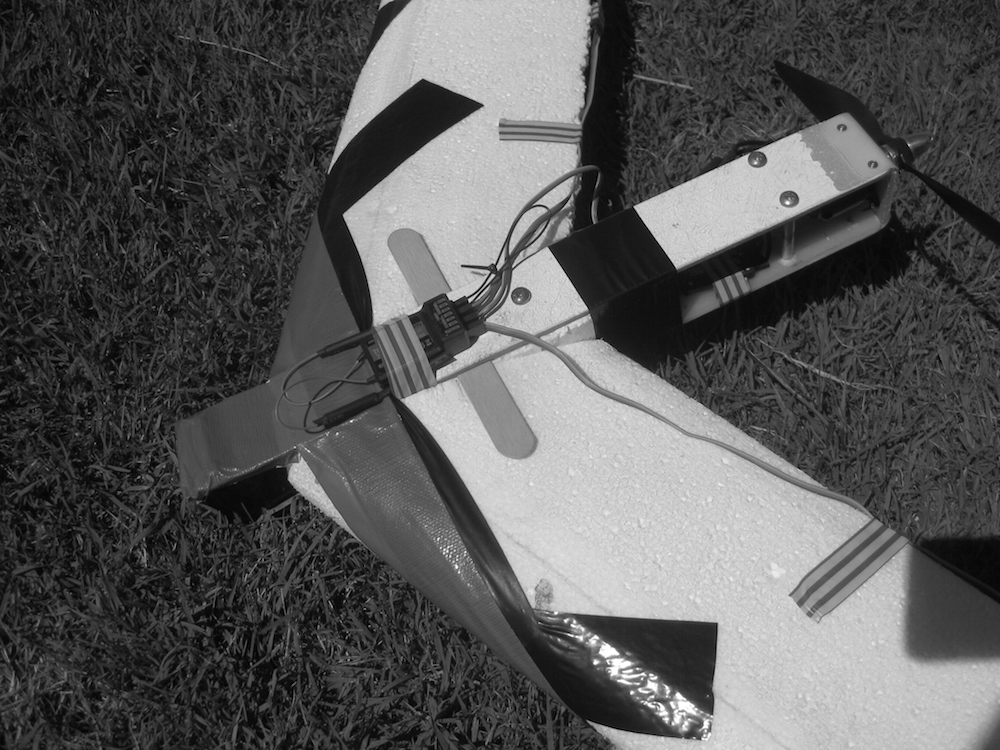
This case was no different. It flew!! The weight shifting worked, but the servos were under powered.
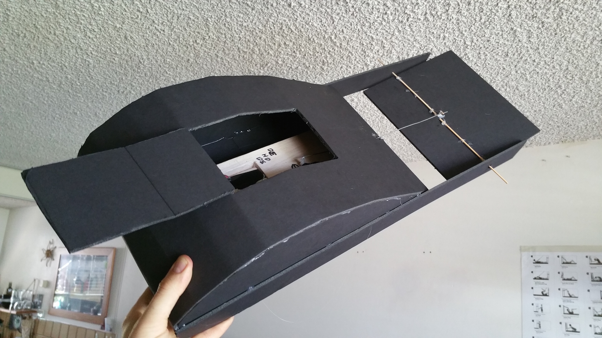
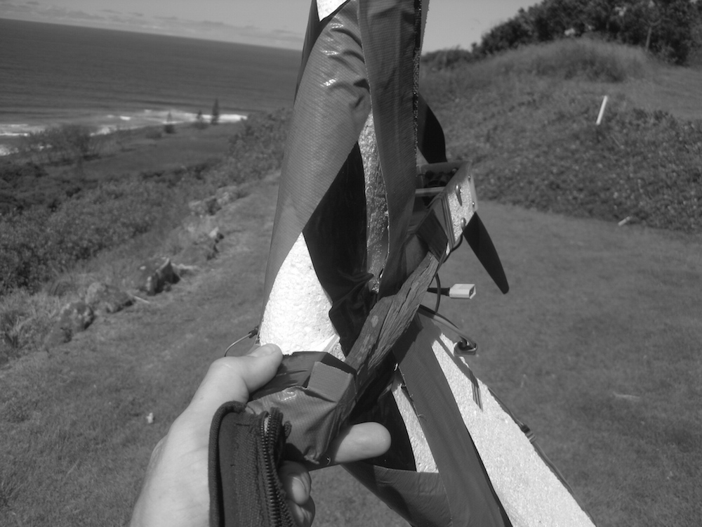
It’s a 1950mm wide wing. The mass is just too much for the hardware. It was not the intention to make the central fuselage so thick (130mm) , I wanted enough swing from the servos to shift the weight far enough during flight. I didn’t want the weight shifting gear hanging out in the air stream. Hence the thickness to enclose the weight shift system.
The 2.5metre wingspan plane I made over 6 months ago had the same problem with hardware. It glud (Yes, glud is now a real word) down the local hill perfectly with no electrical control system mounted. However, upon installing the control system, the 0.25Nm (2.5kg/cm) servos were seriously outgunned.
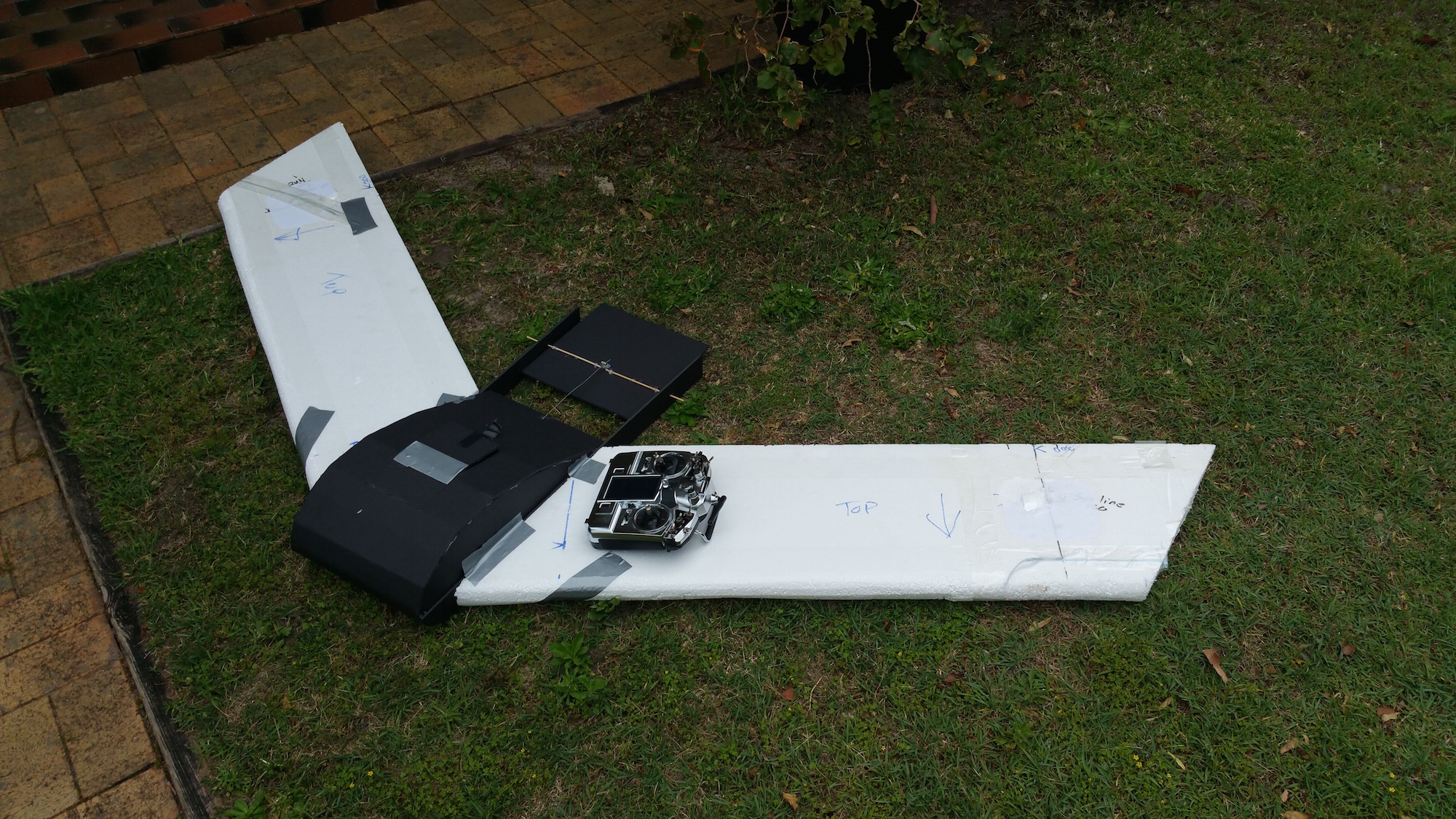
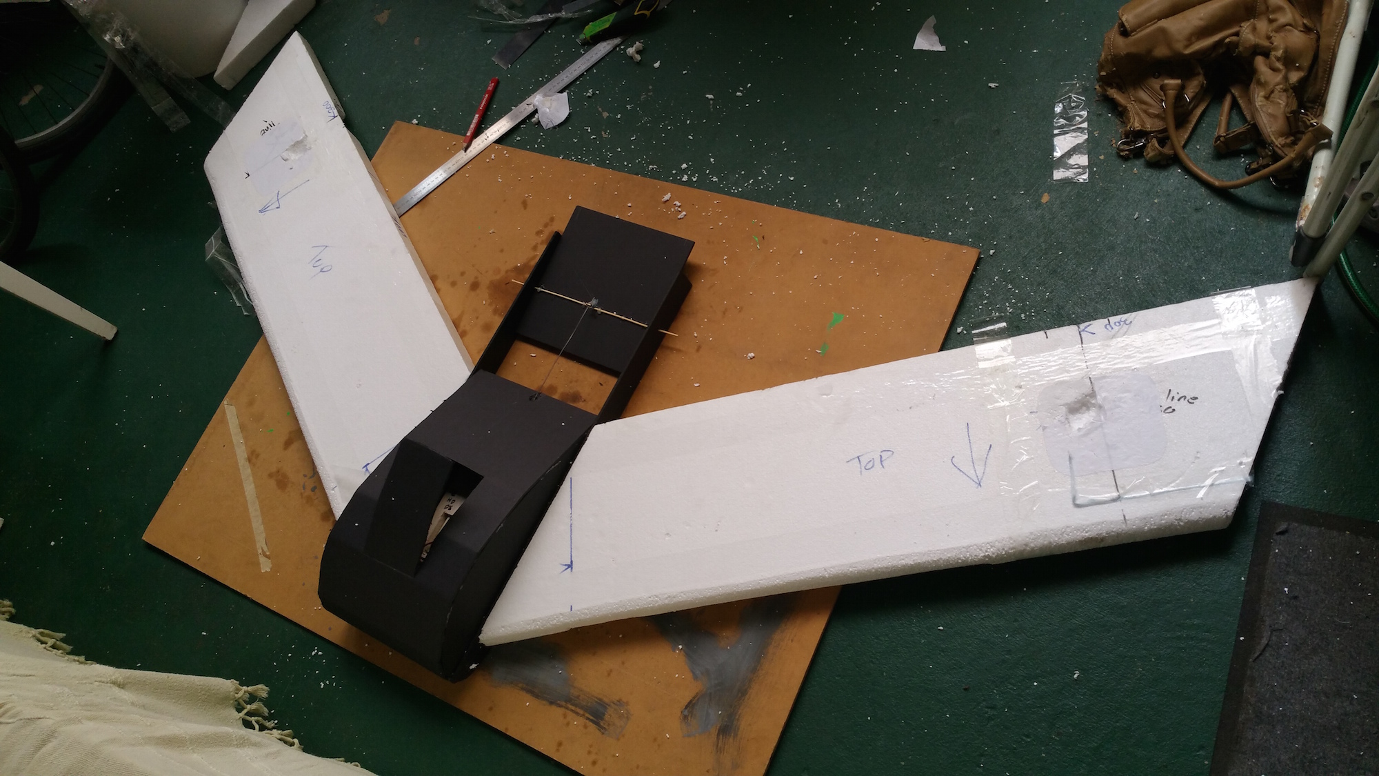
I wanted this to be a easy rebuild wing. By that I mean to have a decent weight shifting fuselage whereby I could just slam on a couple of roughly shaped 50mm thick EPS foam wings. If I destroy them I can just go put on another couple of sheets of foam. A quick general testing platform. If I could control stall, then very slow landings are possible.
The tail plane you see here is to control AOA (Angle of Attack) as there’s not reflex or tip twist. I prefer this method to putting reflex or tip twist in the wing as both involve complex shaping which would contravene the Purpose.
In conclusion. A successful test. I’ll scratch my chin on making a sub 1m wing which can use the small servos. A small wing also fits in the car more easily.


Stepper alternatives
Looks like fast steppers are not readily available. Messing with standard servos now.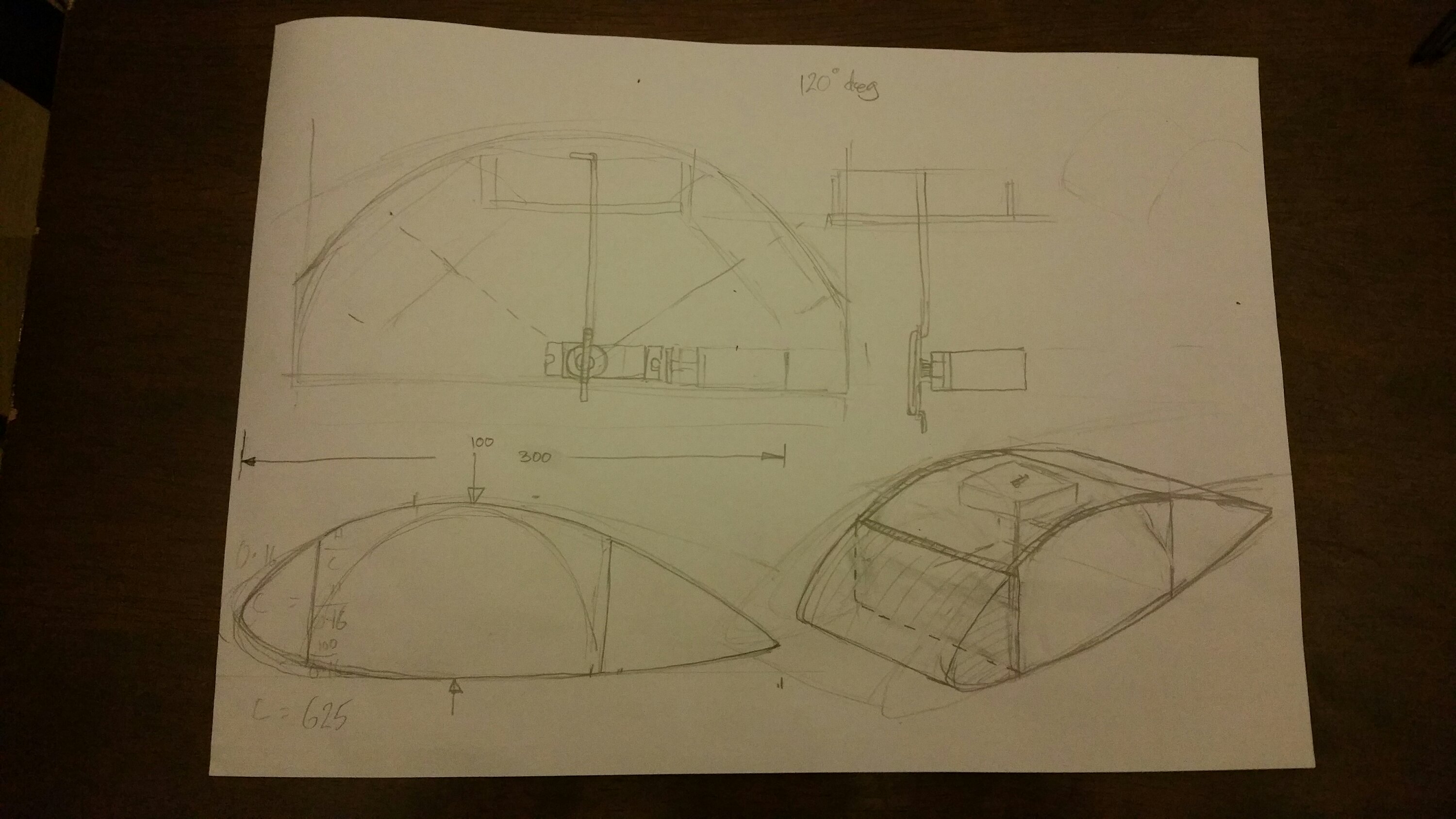
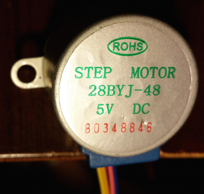
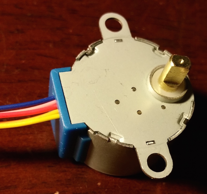
New stepper
It appears this stepper is not fast enough. It only does about 15rpm. NeeeeXt.
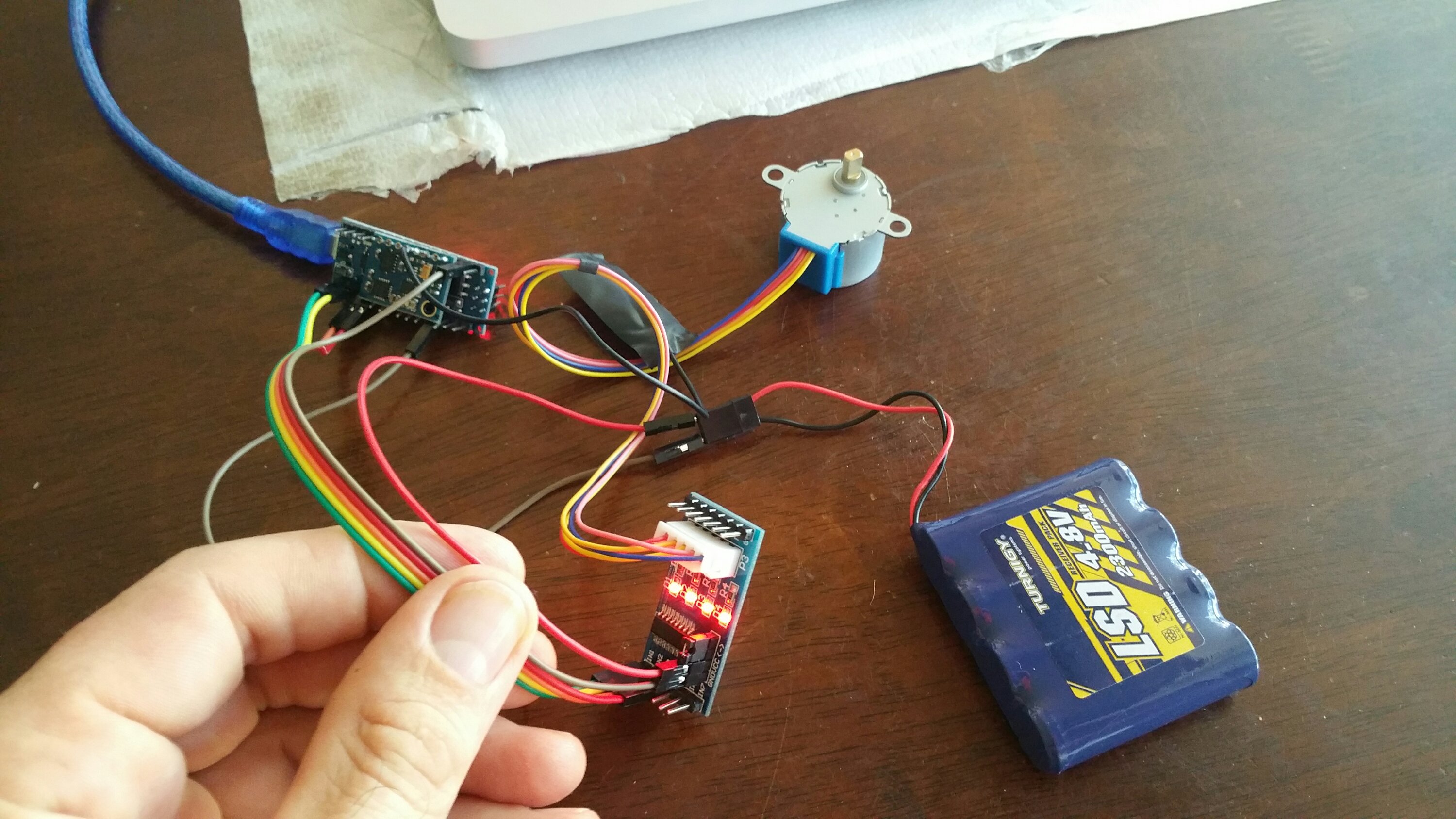
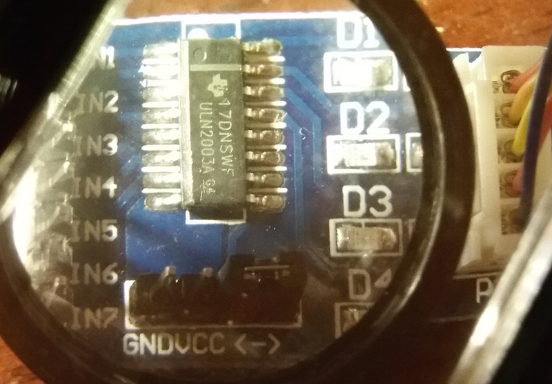
Stepper driver 17DNSWF ULN2003A
Why am I looking at stepper motors?
Well with pretty much all planes we alter the shape of the airfoils to move the centre of lift (COL) relative to the centre of gravity (COG). In this I hope to do the reverse and change the COG relative to the COL. Much like a hang glider or windsurfer does. Thus we can try many more wing types more quickly as we won’t have to deal with making flaps, inserting control horns, mounting servos etc.
Let’s see how we go.
I bought this stepper and hardware driver off Ebay for about $AUD4-.
Chip marking
17DNSWF
ULN2003A
which appears to be a regular Darlington array. This is the data sheet link

Playing with the GY-85
I am trying to make a head tracker for the FPV setup on our slope soaring gliders, as we need to be able to look around to find the cliff edge when gliding. If you’re more than about 30m out, you can be falling out of the sky. With a camera just facing forward, there is no way of telling where you are in the sky relative to the cliff edge and thus the air currents.
From the RCgroups forum post link:
This link points out that the GY-85 which I ordered from DX.com based on Dennis’ initial forum post is not the same as it was some 6 years later. The GY-85 I bought does not have the same magnetometer chip on it. So the headtracker code from this forum does not work on the yaw axis.
The PCB I bought has the QMC5883L chip set instead of the HMC5883L chip set by Honeywell.
I dug up the data sheet and some code for the QMC and the code seems to work well enough in all axis’ . It doesn’t seem to isolate any particular axis fully, but I’m sure with some filtering I could make it more accurate. However it was getting on midnight so I stopped playing with the board and software and decideed to focus on what I was doing.
The i2C bus address was obviously incorrect in Dennis’ code for the QMC chip set. –> Fixed that.. good.
But the QMC works slightly differently and has a different library to the original head tracker code. For the sake of $AUD15- and the fact I could get an IMU board out of Melbourne, I took the time efficient path and ordered the GY-85 board with the HMC chip set below. You can see the
L883
2133
Markings of the HMC5883L chip in the image below.


I ended up ordering this GY-85 from ebay and the images show the Honeywell chip comes with it. Fingers crossed it’s the correct one.
More on this later. Soon we’ll be slope soaring FPV with a head tracker.
Back to it.
It’s been a while without flying, but a recent revival of enthusiasm has put Gemot back in the sky. 30knots or so at Lennox about a week ago. Awesone flying. Then of course a throng of overconfidence about low passes caused a meeting with the ground cracking the top laminate on the starboard wing and a snapped servo horn on the flap.
Some repairs this morning and we’ll be back in the air in the coming days.

INAV F3 Flight controller arrived


Will have to make some time to put this one into action. Hopefully the telemetry going to the OSD will overcome the issue of knowing where the horizon is in flight when staring up into the big blue. The altitude feedback will be good also. Wouldn’t mind fitting an angle of attack indicator to the OSD, ,,, well one thing at a time.
Zamten – Flying wing with a quad chassis


Prototype from fibre glass panel either side. Joiner tubes –> Tapped some 6.2mm alloy tube with an M5 thread. Joined with M5 (thread length 17mm). Carved wing quickly with 50mm thick EPS foam (12kg/m^3) using 60 grit sand paper.