Posted on

2 axis inline (possibly) aerodynamic head tracker gimbal

Currently working on making this 2 axis head tracker gimbal. Roll is not necessary. It it optimised for FPV slope soaring (gliding). We want it to ultimately sit under an aerodynamic cowl so most of the bumpy edges are not in the air stream. Also both rotation points have their own bolts so that load on landings are not transferred through the servo mechanics as much. This design is for the Runcam Eagle Pro 2.

It’s designed for standard Corona 939MG servos, simple linkage stoppers and galvanised 1.8mm – 2mm fencing wire for pushrods.

Posted on

Dubious GY-85 boards and HMC5883L fix

I ordered 3 different GY-85 boards from 3 different suppliers to find that all of them had the wrong magnetometer in them. Some even advertised their product with the HMC5883L chipset on them, but when they arrived they where the QMC5883L chipset.

After all this effort to find something without the shipping cost / time from the USA I decided to just get the HMC5883L individually and attach it to the I2C bus of the GY-85 board. The individual boards is called the GY-271. I found this supplier in Chullora in Sydney:
GY-271 HMC5883L
It worked just fine and now the head tracker is working.
You’ll see in the image below that the Honeywell HMC5883L chip is defined with the markings
L883
2133

Where as the 6th page of the QMC 5883L manual shows the markings something like
DX
5883
XXXX

QMC5883L datasheet

HMC5883L datasheet

Using the GY-271 compass board by itself

(Also posted in RC groups)

Posted on

Something to put the head tracker in.

I wanted to put the head tracker in some thing. Gemot would only just allow for the head tracker in it and it only had 35mm maximum air flow distortion (i.e. the thickness of the centre foil). The EPS sheets I’ve been buying are 50mm thick which is plenty of air distortion to create heaps of lift. This wing above will also have the fuselage as part of the lifting surface. It will be the same proportions as the wings. Thus making it about 70ish mm thick.

It’s about the same wingspan as Gemot coming it at just a touch over a metre. I’ve learnt that the little 0.25N torque servos (2.5kg/cm) are straining on almost everything when the wing span is over a metre.

This wing also allows for the GRP (Glass Reinforced Plastic) chassis to be pushed inside to convert it to powered flight later. It can be tested gliding and then step across to powered later by sliding in the engine. The V- shaped EPS frame inside should spread the load on impacts with the ground during testing.

About the head tracker. The HMC5883L chip arrived in the post on Friday and I couldn’t wait. Put it together that night. Added the chip into the I2C bus, Added Dennis Frie’s code and away it went. It worked through the Turnigy i10 using the trainer cable and a 10channel RX.


Posted on

The 2 versions of the GY-85 9DOF PCB

This one has the HoneyWell Magneto chip on it.

Chip markings:
L883
2133

And this one has the QMC magneto chip on it:

Chip markings:
DB
5883
7007

It’s difficult to confirm which one you’re going to get from any given online seller as they look very similar.

Posted on

Another dud GY-85

This is the 4th order of the GY-85 and it has the QMC magneto in it again even though the photos on ebay showed the Honeywell chip. Hmm, bit of a fail. RC groups was saying the Honeywell chip is not manufactured any more.

I got the QMC chip working on all 3 axis’, but it uses a totally different code library and thus Dennis Frie’s code doesn’t work with it. Might be time to write some code??

Posted on

Playing with the GY-85

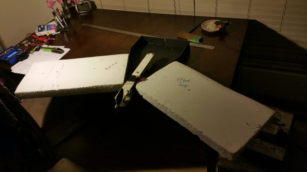
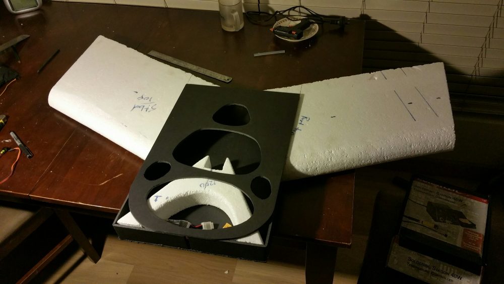
I am trying to make a head tracker for the FPV setup on our slope soaring gliders, as we need to be able to look around to find the cliff edge when gliding. If you’re more than about 30m out, you can be falling out of the sky. With a camera just facing forward, there is no way of telling where you are in the sky relative to the cliff edge and thus the air currents.

From the RCgroups forum post link:

Head Tracker forum post

This link points out that the GY-85 which I ordered from DX.comĀ  based on Dennis’ initial forum post is not the same as it was some 6 years later. The GY-85 I bought does not have the same magnetometer chip on it. So the headtracker code from this forum does not work on the yaw axis.

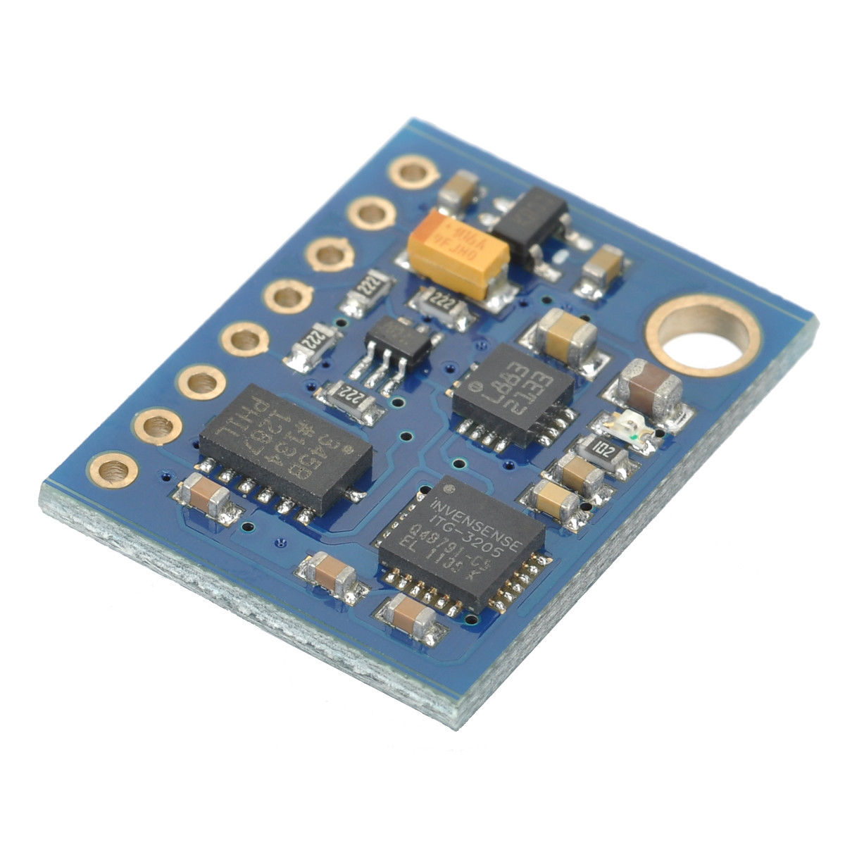
The PCB I bought has the QMC5883L chip setĀ  instead of the HMC5883L chip set by Honeywell.

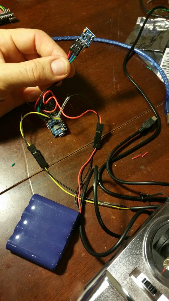
I dug up the data sheet and some code for the QMC and the code seems to work well enough in all axis’ . It doesn’t seem to isolate any particular axis fully, but I’m sure with some filtering I could make it more accurate. However it was getting on midnight so I stopped playing with the board and software and decideed to focus on what I was doing.

The i2C bus address was obviously incorrect in Dennis’ code for the QMC chip set. –> Fixed that.. good.

But the QMC works slightly differently and has a different library to the original head tracker code. For the sake of $AUD15- and the fact I could get an IMU board out of Melbourne, I took the time efficient path and ordered the GY-85 board with the HMC chip set below. You can see the

L883

2133

Markings of the HMC5883L chip in the image below.


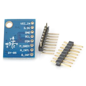
I ended up ordering this GY-85 from ebay and the images show the Honeywell chip comes with it. Fingers crossed it’s the correct one.

More on this later. Soon we’ll be slope soaring FPV with a head tracker.