Objective:
Shift the weight around in the plane, rather than shifting the lift point around using control surfaces (ailerons, elevators, etc).
Purpose:
- Save time on making control surfaces for every wing designed.
- Control the stall point like a hang glider or bird does, to enable controlled stall landings.
- Give the ability to shape and switch wings quickly.
- Reduce the number of weak points caused by embedded servos and control surfaces.
Notes
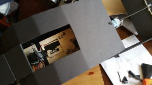
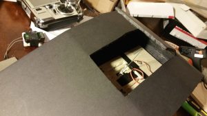
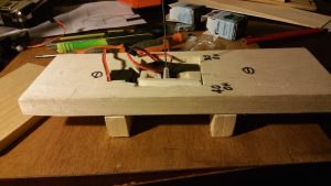
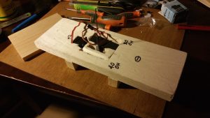
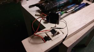
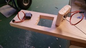
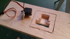
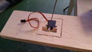
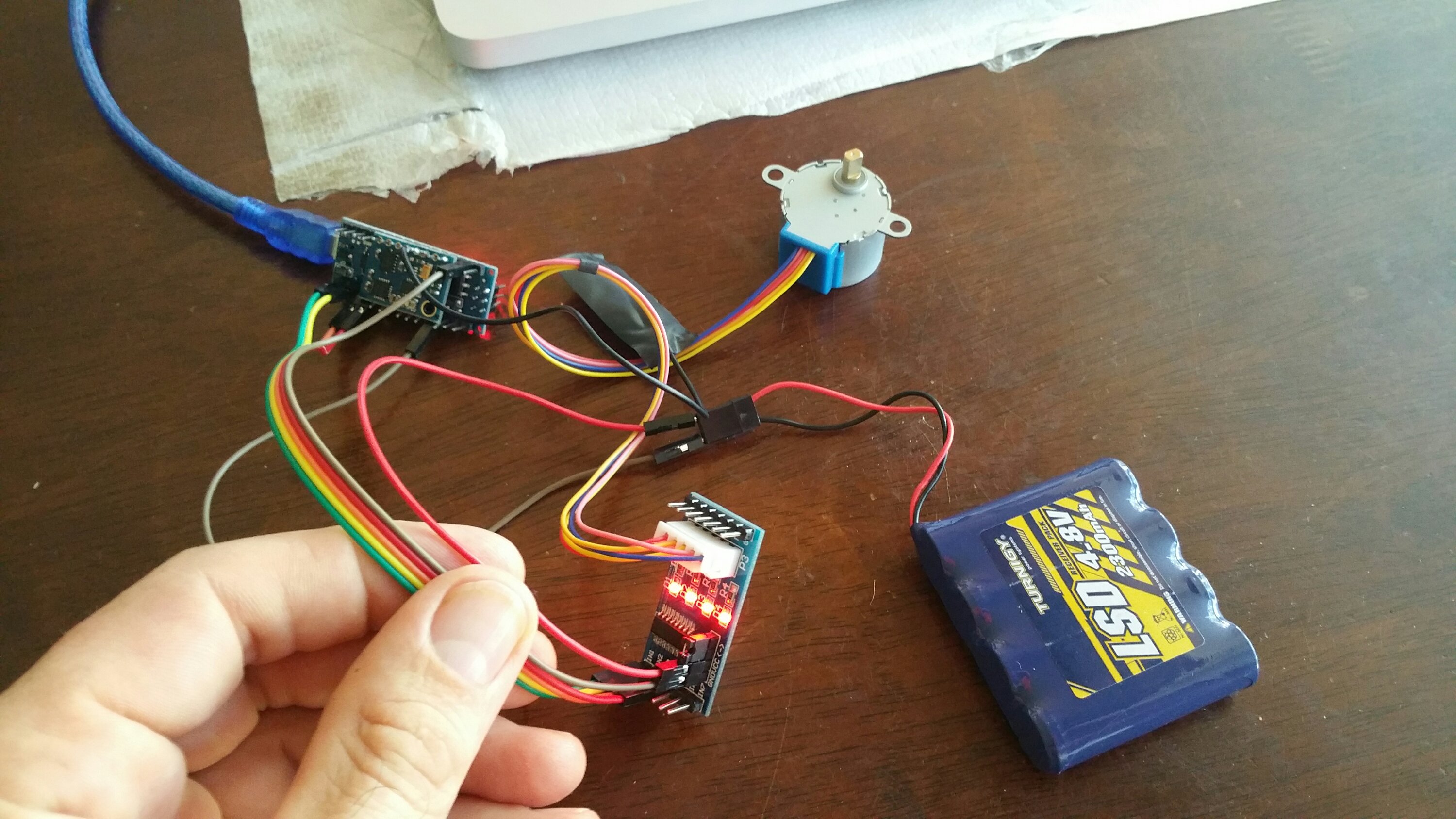
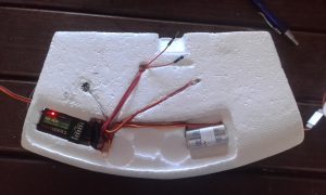
In this attempt on making a flying object which uses weight shift, I decided to use standard servos to see what I could get away with. The stepper motors I want to use would take time to get here and I am impatient on this one.
Definitely the conclusion on the DS939MG servos is that they are not really made for aircraft much bigger than a 1m wingspan. After that the mass just steps up too much and they don’t handle it. Even though I kind of know this when smashing tests together, I do them anyway just to prove concepts.
This case was no different. It flew!! The weight shifting worked, but the servos were under powered.
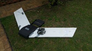
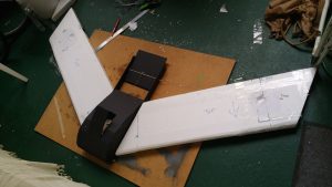
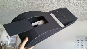
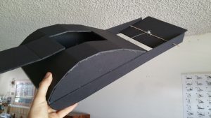
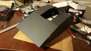
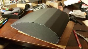
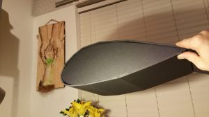
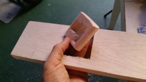
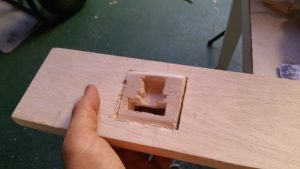
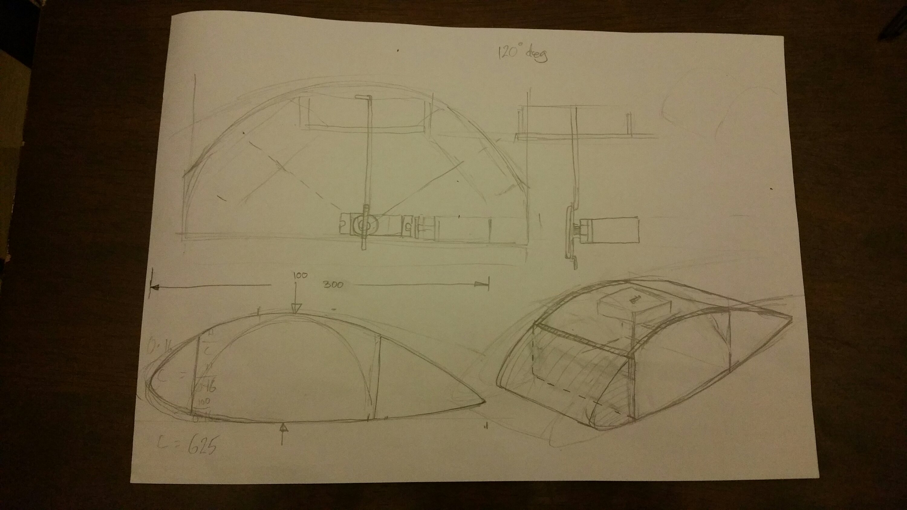
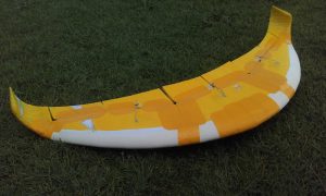
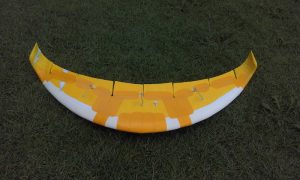
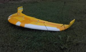
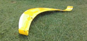
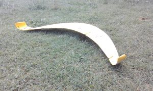
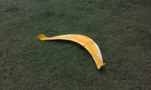
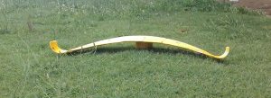
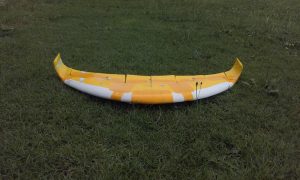
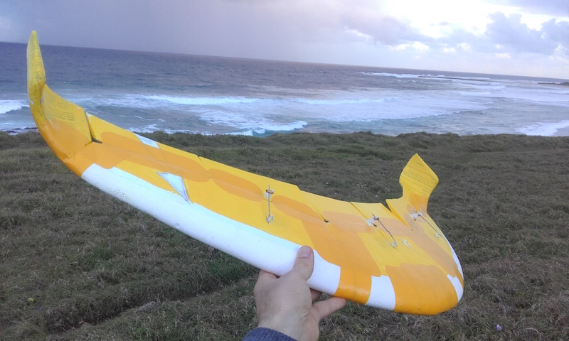
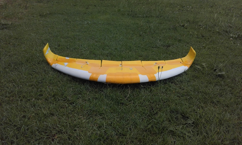
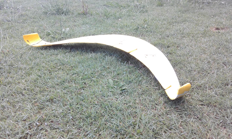
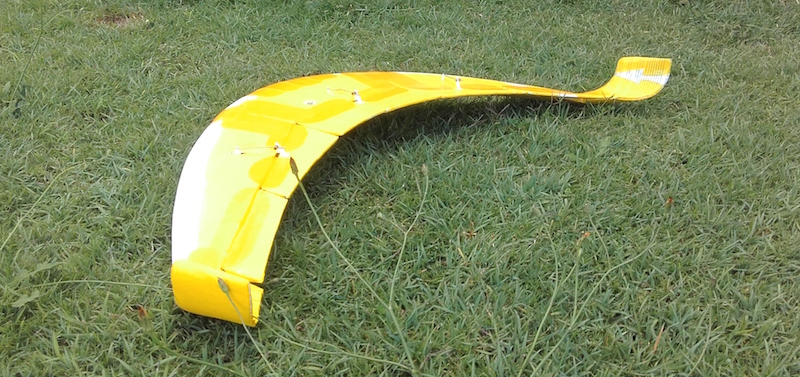
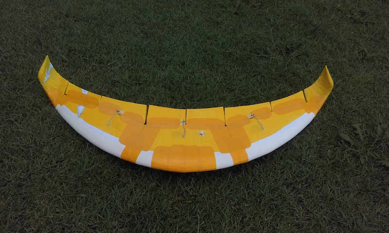
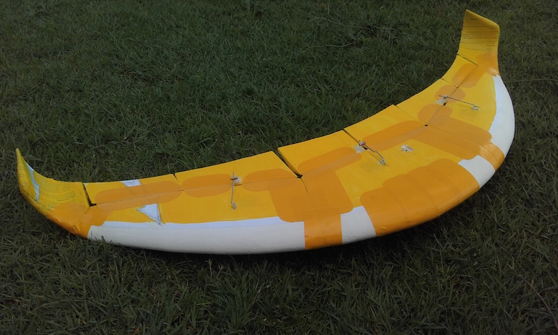
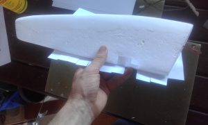
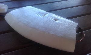
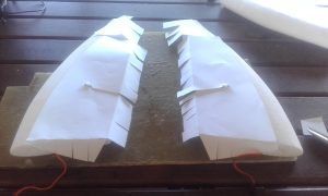
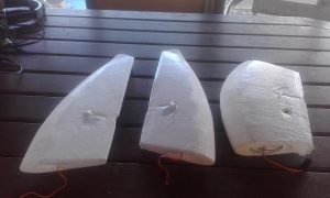
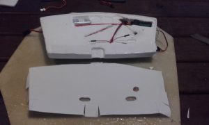
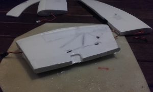
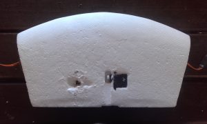
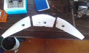
It’s a 1950mm wide wing. The mass is just too much for the hardware. It was not the intention to make the central fuselage so thick (130mm) , I wanted enough swing from the servos to shift the weight far enough during flight. I didn’t want the weight shifting gear hanging out in the air stream. Hence the thickness to enclose the weight shift system.
The 2.5metre wingspan plane I made over 6 months ago had the same problem with hardware. It glud (Yes, glud is now a real word) down the local hill perfectly with no electrical control system mounted. However, upon installing the control system, the 0.25Nm (2.5kg/cm) servos were seriously outgunned.
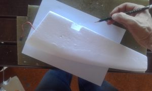
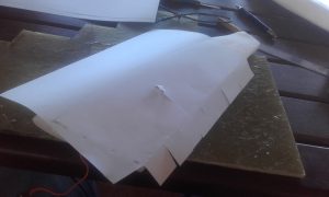
I wanted this to be a easy rebuild wing. By that I mean to have a decent weight shifting fuselage whereby I could just slam on a couple of roughly shaped 50mm thick EPS foam wings. If I destroy them I can just go put on another couple of sheets of foam. A quick general testing platform. If I could control stall, then very slow landings are possible.
The tail plane you see here is to control AOA (Angle of Attack) as there’s not reflex or tip twist. I prefer this method to putting reflex or tip twist in the wing as both involve complex shaping which would contravene the Purpose.
In conclusion. A successful test. I’ll scratch my chin on making a sub 1m wing which can use the small servos. A small wing also fits in the car more easily.

